Add multiple LockNodes (Automatic) - Step-by-Step WO
You do not have to remove the locking devices from the boxes. This setup can be carried out by the installer.
Hardware required:
- QR scanner with DataMatrix support (for name list creation)
- Network switch (ideally with PoE) to connect multiple GatewayNodes
- Separate network setup from other IT networks
NOTE

Procedure does not replace assignment to GatewayNodes
This procedure is only used to assign and programme LockNodes in locking devices to the system as quickly and efficiently as possible. The assignment takes place later (see Automatically assign LockNodes).
NOTE
Not suitable for RS-485 systems
This procedure is not suitable for RS-485 systems.
NOTE
Limitation to LockNodes for the project with name list
Using the name list is optional. Without a name list, however, all LockNodes within reach are added to the system. This also applies to LockNodes which are to be used in other projects (and which for example are stored in the same warehouse at the installer).
- Use the name list.
- TCP configuration completed, ideally with the final IP address association (see Configuring GatewayNodes (TCP)).
- Locking devices labelled and scanned (see Creating, expanding and importing a name list).
- Name list created (see Creating, expanding and importing a name list).
- Locking devices with LockNodes can be accessed via connected GatewayNodes.
- SmartIntego Manager opened.
- Right-click on the navigation root (WaveNet_XX_X).
- The window Administration opens.
- Select the option
 Read list of nicknames.
 - Click on the button OK.
- Window Administration closes.
- Select the name list.
- Import the name list.
- All chip IDs in SmartIntego Manager are checked and updated with the assigned name from the name list.
- Name list remains loaded in the background during the entire session. All newly found GatewayNodes and LockNodes are automatically named.
- Right-click on the navigation root (WaveNet_XX_X).
- The window Administration opens.
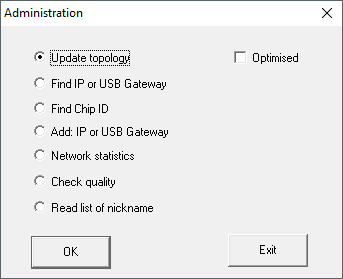
- Select the option Update topology.
- Click on the button OK.
- Window Administration closes.
- Query opens for host names.
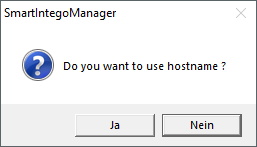
- Reject the use of host names (whenever possible, always work with the IP address to reduce dependency on DNS servers).
- Query for host name closes.
- The window for specifying the maximum number of LockNodes per GatewayNode opens.
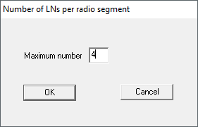
- Specify the maximum number of LockNodes per GatewayNode.
NOTE
Information on specifying the maximum number of LockNodes per gateway
The number of LockNodes supported can be limited by the integrator system. This particularly applies to integrator systems with hardware controllers (limitation of the number of locking devices per controller).
- In this step, specify 50% of the maximum locking devices supported by the integrator system.
- This leaves capacities free for later moving the LockNodes to the GatewayNodes.
- In this example, the integrator system supports eight LockNodes per GatewayNode. Therefore, the number is limited to four LockNodes per GatewayNode.
- Click on the button OK.
- Window for specifying the maximum number of LockNodes per GatewayNode closes.
- The window Select node opens.
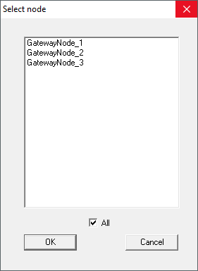
- Select all connected GatewayNodes.
NOTE
Multiple Pass Allocation
Sometimes it is not possible to connect all GatewayNodes at the same time. However, the assignment should take place at all GatewayNodes.
- Stake out the previous GatewayNodes.
- Instead, connect the unassigned GatewayNodes.
- Select the connected GatewayNodes.
- Repeat the run.
- Run again shows all GatewayNodes found.
- Select only GatewayNodes that are not yet added or configured.
- Click on the button OK.
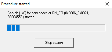
- LockNodes are searched for and added using the name list (duration: approximately two minutes per GatewayNode).
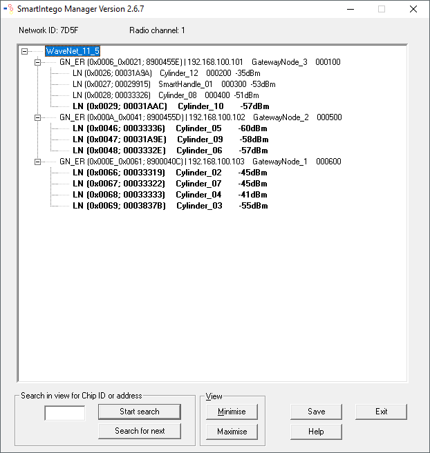
- Added LockNodes are displayed in Smartntego Manager.
- Click on the button Save.
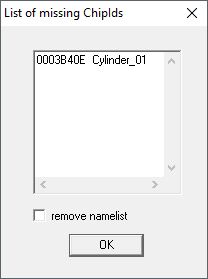
Add unattached or unallocated LockNodes later
It is possible that LockNodes from the name list have not been reached or not assigned:
Manually add these LockNodes with one of the two options:
- Rerun: Add multiple LockNodes (Automatic)
- Add individually: Add individual LockNodes
In the example, the LockNodes was incorrectly in the name list for illustration purposes.
SmartIntego Manager shows you the following information for the locking device:
- WaveNet address
- Chip ID
- Name
- Device Address
- Last RSSI value measured by SmartIntego Manager in dBm
NOTE
Data loss due to improper termination
The data is not transferred to the SmartIntego tool (WO) until the SmartIntego Manager is properly ended. After saving, the files are permanently saved in the * ikp file in the SmartIntego tool (WO).
- Click on the Save button.
- Close SmartIntego Manager correctly using the button Exit.