RouterNode: Digital output - WaveNet
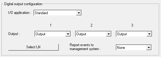
You can select the following entries from the dropdown list :
Standard | Standard entry: |
In the dropdown list , you can set when the output in the RouterNode triggers:
Output | Standard entry: The RouterNode does not switch the output. You can switch the output manually (see IO Status and LockNode responsiveness). |
Authorised | The output switches at one or more freely selectable locking devices with a LockNode assigned to the RouterNode for about one second in case of an authorised identification medium. The identification medium must be present in the locking system. |
Unauthorised attempt | If an unauthorised identification medium is present on one or more freely selectable locking devices with a LockNode assigned to the RouterNode, the output switches for about one second. The identification medium must be present in the locking system. |
All LN events | The output switches at any identification medium at one or more freely selectable locks with a LockNode assigned to the RouterNode for about one second. The identification medium must be present in the locking system. |
Input receipt short (at all LockNodes) | The output switches when the response (see RouterNode: Digital input) to a signal at the corresponding input on all LockNodes has been performed (=input event) for about one second. |
Input receipt static (at all LockNodes) | The output switches when the response (see RouterNode: Digital input) to a signal at the corresponding input has been performed on all LockNodes. As long as the input event is present after the response is completed, the output remains switched. |
Output 1 | O1 | Relay output, consisting of O1.NC, O1.NO and O1.COM
When the output is switched, the relay picks up and changes from the idle state to the energized state. |
Output 2 | O2 | Digital output (Open Drain), max. 12 VDC, max. 100 mA (resistive load) When the output is switched, the output is connected to the ground potential. |
Output 3 | O3 | Digital output (Open Drain), max. 12 VDC, max. 100 mA (resistive load) When the output is switched, the output is connected to the ground potential. |
With the button Select LN you can open the window Select LN to configure I/O settings. Select the LockNodes in locking devices here. Authorised access or unauthorised access attempts at these locks (LockNodes) are forwarded to the LSM.
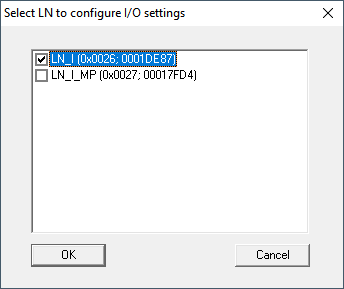
In LSM, you can react to the forwarded event using the Event manager.
In the dropdown list (WNM IO Config), you can set which events at the LockNodes selected previously are forwarded to LSM:
None | Default entry. There is no event and no forwarding. |
Authorised | Authorised access attempts at the marked locks (LockNodes) are forwarded to the LSM (= event that is forwarded to the LSM). |
Unauthorised attempt | Unauthorised access attempts at the marked locks (LockNodes) are forwarded to the LSM (=event that is forwarded to the LSM). |
All LN events | Authorised accesses and unauthorised access attempts at the marked locks (LockNodes) are forwarded to the LSM (=event that is forwarded to the LSM). |
Alternatively, you can also set directly on the LockNodes whether the LockNodes forward events to the RouterNode (see LockNode).
Select the event here that triggers forwarding to LSM. If the event specified here (Authorised, Unauthorised attempt or All LN events) occurs at the locking devices (LockNodes) that you have previously defined (Select LN), the event is forwarded to the LSM.
NOTE

Same event for forwarding
You cannot select LockNodes (and thus the lock in which the LockNode is built in) and thus exclude them from event forwarding. If you use event forwarding, the same event applies to all LockNodes selected (in Select LN).
For example, you cannot only forward authorised accesses for one LockNode and unauthorised access attempts for another.