Central output router - WaveNet
The availability of this function is firmware dependent (see Firmware information).
You can read out the firmware version of your RouterNode via the browser interface (see Browser interface) or the OAM tool (see Updating firmware).
Adding the central output router
In RingCast you can configure any second generation RouterNode (with Ethernet interface, WNM.RN2.ER.IO from firmware version 40.10) as central output router. The central output router first collects the received input acknowledgements of all other Ethernet router nodes (ER) involved in the RingCast and only then sends its own input acknowledgement or sets the output as set in RouterNode: Digital output. All other RouterNodes set the input acknowledgement / output as previously set.
Transmission takes place via Ethernet. Its output is therefore always switched as the last output of the entire RingCast and indicates that all locking devices involved in the RingCast via Ethernet RouterNodes have received the command.
NOTE

Central output router in RingCast with R/CR router nodes
The central output router receives the input acknowledgement of the participating router nodes exclusively via an Ethernet connection. The central output router therefore ignores the status of router nodes that are not Ethernet router nodes (.ER). If you are using the central output router and your RingCast also contains router nodes without an Ethernet interface, the central output router's input acknowledgement only means that all locking devices assigned to an Ethernet router node have received the command.
- Check the status of other router nodes (R/CR) independently of the central output router manually (see Test reachability (LSM) and RouterNodes or IO Status and LockNode responsiveness).
If the central output router does not set its input acknowledgement or does not switch its output, this may be due to these reasons, among others:
- One or more RouterNodes have not received the data packet.
- One or more RouterNodes have not reached one or more LockNodes.
- Ethernet connection to one or more RouterNodes is interrupted. The RouterNodes could have received the data packet wirelessly, but could no longer return their input acknowledgements due to the interrupted Ethernet connection.
- Right-click on the entry "WaveNet_xx_x" in the WaveNet Manager.
- The window Administration opens.
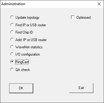
- Select the option
 RingCast.
 - Click on the button OK.
- The Administration window closes.
- The window Edit radio domains opens.
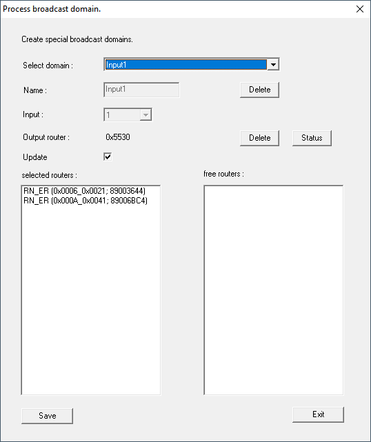
- In the drop-down list select the name of the domain whose central output router you want to specify.
- Select the RouterNode you want to set as the central output router.
- Click on the button Set.
- Click on the button Save.
- Click on the Exit button.
- The central output router is set.
Delete central output router
Without a central output router, all RouterNodes (including the former central output router) set the input acknowledgement / output as previously set.
- Right-click on the entry "WaveNet_xx_x" in the WaveNet Manager.
- The window Administration opens.
- Select the option RingCast.
- Click on the button OK.
- The Administration window closes.
- The window Edit radio domains opens.
- Click on the lower button Delete.
- Central output router is flagged for deletion.
- Click on the button Save.
- Click on the Exit button.
- Central output router is deleted. The completion of the RingCast is no longer displayed.
Report completion of RingCast to LSM
RouterNodes cannot report the input acknowledgement (or the switching of an output) directly to LSM. To do this, use a digital input and forward its status to LSM (see RouterNode: Digital input). This allows you to react to the successful completion of a RingCast in the event manager.
This illustration shows the wiring when the input acknowledgement is output on O3 or O2. Connect O3/O2 to a free digital input as shown and forward this to the LSM. The switching behaviour is inverted by the pull-up resistor:
- Input acknowledgement active: Level at digital input 0 (Low)
- Input acknowledgement not active: Level at digital input 1 (High)
This illustration shows the wiring when the input acknowledgement is output on O1. Connect O1 to a free digital input as shown and forward this to the LSM.