Configuration - SmartRelay 3 system
You can use the LSM software to programme and configure the controller and the SREL3 ADV system. Other SREL3 ADV system components do not need to be programmed.
NOTE

Initial programming via USB
The controller can be addressed via TCP/IP. However, no IP address is configured in storage mode. That is why initial programming, during which an IP address is assigned, must be carried out with a USB connection.
- Components connected to power.
- Controller connected to computer with USB cable.
- Reader connected to the controller (see wiring).
- LSM installed and launched as administrator.
- System requirements met.
- Communication nodes set up (VN Host and CommNode; see LSM manual).
- Create a new G2 locking system.
- Click on the ... button to open the locking system settings.
- Change to the G2 card management tab.
- Open the drop-down menu.
- Select your card type.
- Open the drop-down menu.
- Select a configuration.
NOTE
Suitable configurations
AV configurations are the only suitable ones for use in a locking system with an SREL3 ADV system.
- Click on the Apply button.
- Click on the Exit button.
- Matrix screen is visible again.
- Create a new G2 Smart Relay 3 locking device.
- Double-click on the SmartRelay 3 entry in the matrix to open the settings.
- Select the IP settings tab (see Establishing IP settings for help on IP settings).
- Enter an IPv4 address.
- Enter an IPv4 subnet mask.
- Open the drop-down menu.
- Select a suitable communication node. If you haven't yet created a communication node for the service, you need to add one first. See Creating a communication node.
NOTE
Selecting the communication node
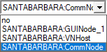
If you are using a CommNode server and a VN host server (use of tasks or events in addition to the virtual network), then choose the CommNode server entry here.
If you want to use a VN host server (use of the virtual network), then select the VN host entry here.
If you do not wish to use either, then select the GUI node entry here.
- Click on the Apply button.
- Click on the Exit button.
- Right-click on the SmartRelay 3 entry in the matrix to open the context menu.
- Select the entry.
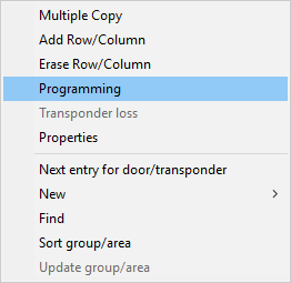
- Select USB link to the TCP nodes in the programming window.
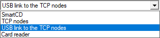
- Click on the Programming button.
- Programming launches.
- Wait for programming.
- Use Network to select the entry.
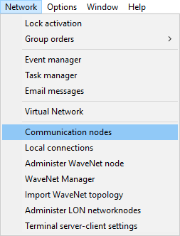
- If you have created more than one communication node, change to the communication node you have just created. Use the
 or
or  and
and  or
or  buttons.
 - Terminate the SimonsVoss VNHost Server or SimonsVoss CommNode Server service.
- Click on the Config files button.
- Open Windows services.
- Save the service's configuration files locally on your computer.
- Copy the configuration files saved locally and add them to the service's installation folder (default: C:\Programme (x86)\SimonsVoss\VNHost or C:\Program Files (x86)\SimonsVoss\CommNodeSvr_3_4).
NOTE
All three XML files must be copied directly to the installation folder, not to a sub-folder.
- Launch the SimonsVoss VNHost Server or SimonsVoss CommNode Server service again.
NOTE
Click on the Ping button to check whether the service is running and responding. If the service responds, you can continue. If it does not, try to launch the service again.
- Click on the Transmit button in LSM.
- Controller can be reached via network.
- Terminate the SimonsVoss VNHost Server and SimonsVoss CommNode Server services.
- Create your backup again (see LSM manual).
- Launch the SimonsVoss VNHost Server and SimonsVoss CommNode Server services again.
- Controller can be reached via network and flashes blue.