Controller - SmartRelay 3 system
The controller can be installed horizontally or vertically. You can use the integrated fastening holes to install it safely and easily in a horizontal position (see Drilling templates).
IMPORTANT
Adverse effect on reception due to interferences
This device communicates wirelessly. Wireless communication can be affected or may fail due to metal surfaces or interference.
- Do not fit the device to metal surfaces.
- Keep the device away from sources of electrical or magnetic interference.
Unauthorised access
The relay in the controller can be short-circuited by unauthorised persons.
- Mount the controller with the relay in an environment that is protected against unauthorised access.
Unauthorised switching of the relay by magnet
The relay can switch unintentionally due to strong magnets nearby.
- Mount the controller with the relay in an environment that is inaccessible to unauthorised persons with magnets.
- Alternatively, operate the relay permanently activated (invert output and use NC+COM instead of NO+COM).
Malfunctions due to weather conditions
The controller is not protected against splash water and other weather influences.
- Mount the controller in an environment that is protected from the weather.
- Press the cover in as shown and remove it.

- Hold the base plate in the desired position and mark out the drill holes.
- Drill the necessary holes using a suitable drill bit.
- Use suitable fasteners and screw them into the base plate.
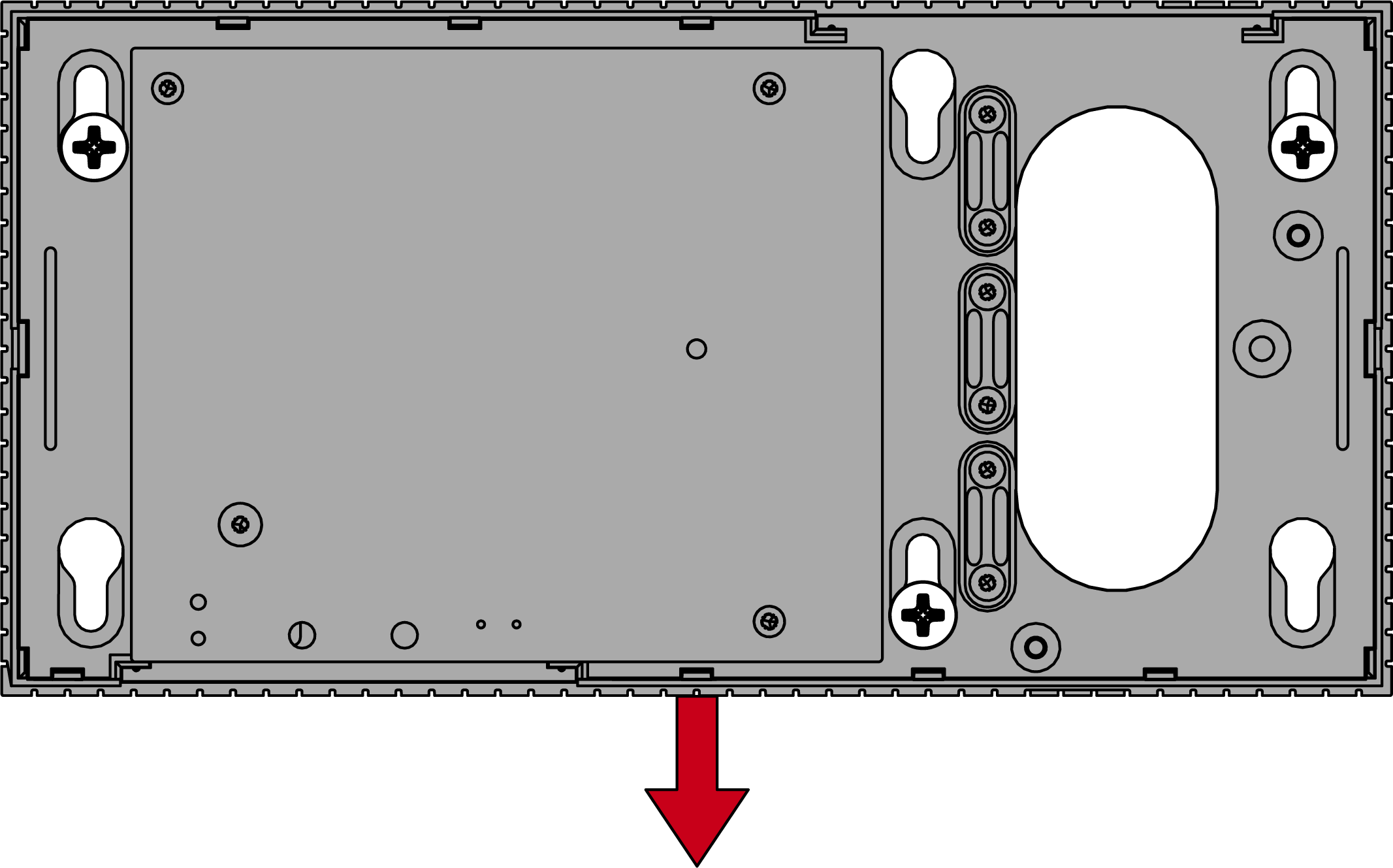
- Place the base plate so that the screw heads pass through the recesses.
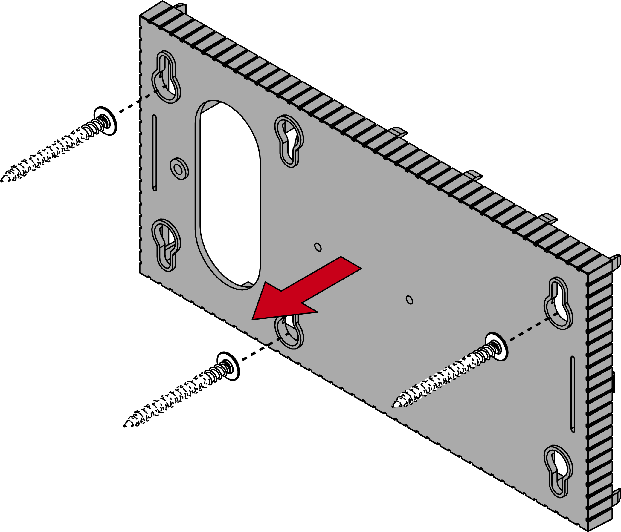
- Move the base plate so that the screw heads slide over the grooves.
CAUTION

Additional fixation for ceiling mounting
The device may fall from the ceiling.
- Tighten the screws after sliding on the base plate.
- Put the lid back on the base plate.
- Installation complete.
If necessary, you can also modify the housing:
- Power supply disconnected.
- Push the ribbed area laterally inwards and remove the housing cover.
- Check the required width of the housing opening. The height of the opening is approx. 7 mm. Each removed bar widens the opening by 4 mm.
- Select a location where you want to remove the bars.
IMPORTANT
Insufficient fit due to removed clips
The housing cover is positioned and held by clips on the webs. If you saw off or break off these clips, the housing cover will no longer be held at this point.
- Do not remove any bars that have a clip over them.
- Do not damage clips during sawing.
- Use a suitable saw to saw through the bars at both ends of the desired opening to the base plate.
- Bend the bars back and forth at the desired opening until the bars break.

- The housing is designed to be mounted on a surface.