Conventional fastening system for Scandinavian Oval DP - SmartHandle 3062
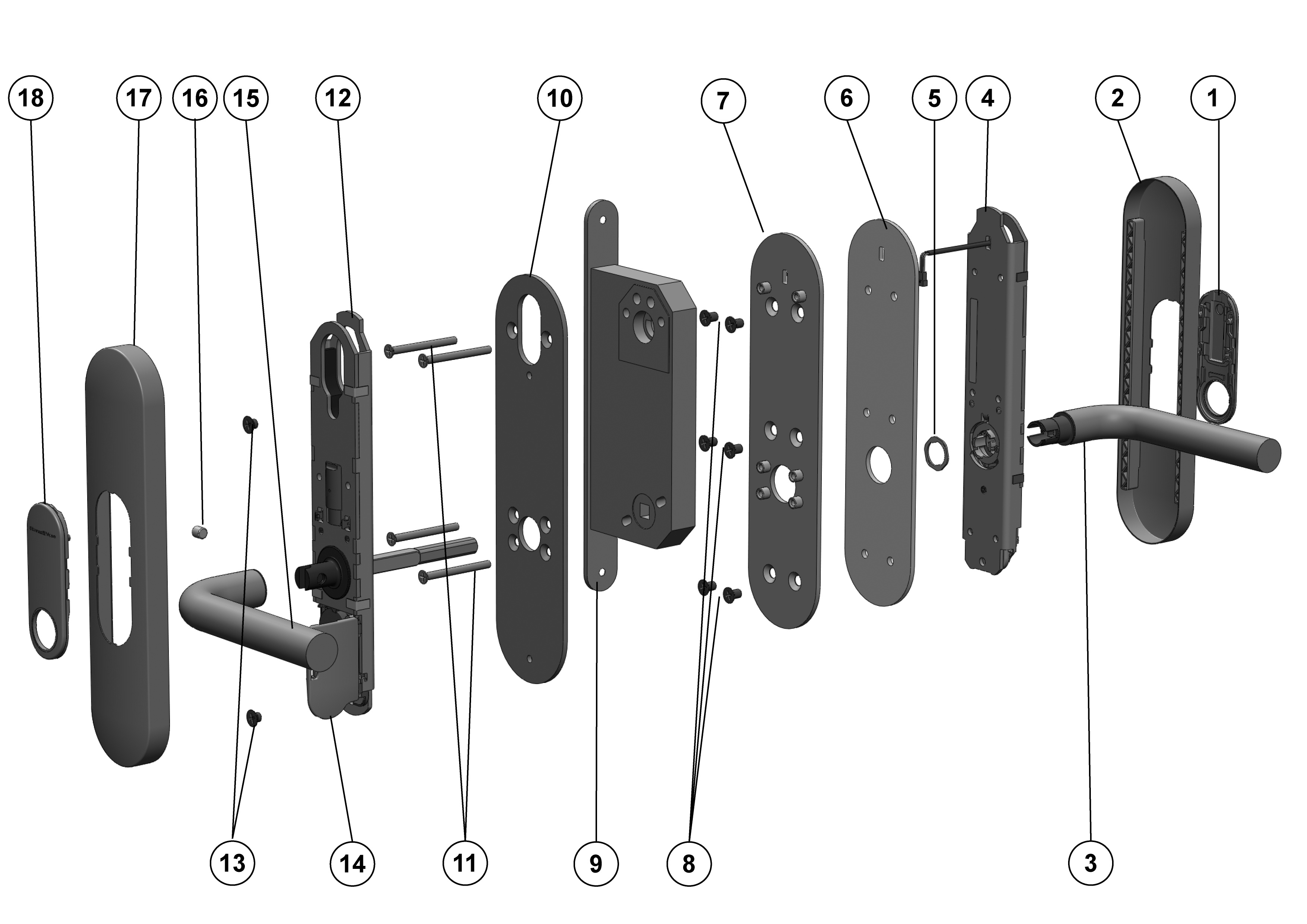
Key:
- Inlay
- Inlay
- Outside handle
- Outer fitting
- Handle fastener piece
- Drilling protection plate
- Adapter plate for outer side
- Screws
- Door lock (not included in the scope of supply)
- Adapter plate for inner side
- Screws
- Inside fitting
- Screws
- Lower battery
- Inside handle
- Inside hexagon screw
- Inlay
- Inlay
Installation:
- Optional: handles, escutcheons, fittings and other door furniture fitted to the door are to be removed.
- SmartHandle 3062 is partly assembled when supplied; see "Disassembly".
- Push inlay (1) onto the outer handle (3). Depending on the handle model, it may not be possible to fit it once the handle is installed.
- Insert outer handle (3) horizontally into the outer fitting (4), placing it in the direction that you require, depending on whether it is a DIN left-hand or right-hand door.
- Place handle fastener piece (5) into position (see Diagrams 2 and 3).
- Hold the outside handle (3) and use the spanner to rotate the fastener piece (5) about 75° to the right until it fits into position (Diagrams 4 and 5). If you do not fit it correctly, the handle may come loose again.
- First, you must adjust the four supplied mounting screws (11) to the door thickness using the following formula. The screws (11) have also been treated with thread-locking fluid to prevent the handle coming loose due to vibrations, for example. Important: this fluid hardens within 24 hours of the screws being fastened for the first time. If the screws are undone again, the fluid no longer secures the screws.
NOTE

Required screw length = door thickness + 4 mm The tolerance is ± 1 mm.
- The outer fitting (4) is mounted from the outer side of the door. Push the cable from the outer fitting through the small, upper hole in the drilling protection plate (6).
- Push the cable from the outer fitting through the small, upper hole in the outer adapter plate (7).
- Place the drilling protection plate (6) flat on the outer adapter plate (7), so that all holes are superimposed over one another.
- Place both plates flat on the fitting (4), so that all holes are superimposed over one another.
- Use the six drilling protected screws (8) to fasten the outer adapter plate (7) to the outer fitting (4) and then tighten firmly by hand, using about 5-7 Nm.
- Push the cable from the outer fitting through one of the two upper holes in the mortise lock.
- Push the outer fitting (4) onto the door, making sure that the cable does not get caught or damaged in any other way.
- Hold the outer fitting (4) firmly and then press the inner side adapter plate (10) against the door from the inside.
- Use the four screws (11) to join the inner side adapter plate (10) with the outer fitting (4) from the inside, ensuring that the fitting can still move freely.
- Position the fitting parallel to the door leaf; otherwise, you may not be able to mount the inside fitting (12). If this is the case, you will need to re-align the fitting.
- Fasten the screws (11) until the adapter plate (10) lies flat against the door.
- The inside fitting (12) is mounted onto the inner surface of the door. Push the inner fitting spindle through the mortise lock (9) retainer slot and push the inner fitting (12) until it is flush with the door. In doing so, push the 2-pole cable through the cylinder opening in the mortise lock and ensure that it does not get caught.
- Press outer and inside fittings together, so that they are both flush against the door.
- Press the electronics module cover lid in the inside fitting carefully out of its bracket and fold back horizontally. Make sure that the electronics are not subject to mechanical load and are not damaged in any other way.
- Carefully remove the lower battery (14) from the holder. Use clean gloves free of fat or grease to handle batteries.
- Use the two screws (13) to fasten the inside fitting (12) to the adapter plate (10), using about 5-7 Nm of force.
- Insert the lower battery (14) with the positive terminals facing away from the door into the brackets; in doing so, insert the batteries under the black retaining collar first. Use clean gloves free of fat or grease to handle batteries.
- Carefully lock the electronics cover lid back into place.
- Connect the 2-pole cable from the outer fitting to the 2-pole cable from the inside fitting. This cable can only be inserted in one direction. Do not pull on the cables while doing so; just carefully secure the plug-in connection into position. Optional: Connect the two-pole cable of the additional electronic module on the outer side with the respective cable of the inside fitting.
- The 2-pole cable from the outer fitting may hang freely; when mounting the outside cover (2) onto the fitting, ensure that the cables do not get caught or broken. Do not pull on the cables. The second cable is optionally used to connect the LockNode circuit board.
- Check that the outer handle can turn easily; if it does not, there may be a problem with the mortise lock (9) or the handle may have been fitted incorrectly. In case of doubt, disassemble components and start again from Step 4.
- Push inlay (17) onto the inside handle (15). Depending on the handle model, it may not be possible to fit it once the handle is installed.
- Push inside handle (15) onto the inner fitting (12) fastening flange until it will go no further.
- Tighten the inside handle (16) hexagon screw firmly by hand, using about 5-7 Nm.
- Push the cover (17) over the inside handle (15).
- Carefully push the inlay (18) through the opening in the inside cover (17).
- Push the cover (17) onto the inside fitting (12), so that it is flush with the door. The cover is not symmetrical; look carefully at the marking to ensure correct positioning.
- Click the inlay (18) carefully into the cover (17).
- Push the cover (2) over the outside handle (3). The cover is used as an antenna for the LockNode.
- Carefully push the inlay (1) through the opening in the outside cover (2).
- Push the cover (2) onto the outer fitting (4), so that it is flush with the door. The cover is not symmetrical; look carefully at the marking to ensure correct positioning.
- Click the inlay (1) carefully into the cover (2).