Installation - SmartHandle 3062
- SmartHandle cover and inlay removed (see Quick Start Guide or SmartHandle manual).
- Grounding completed (e.g. on radiator)
- Place the LockNode on the plate of the SmartHandle subassembly as shown.
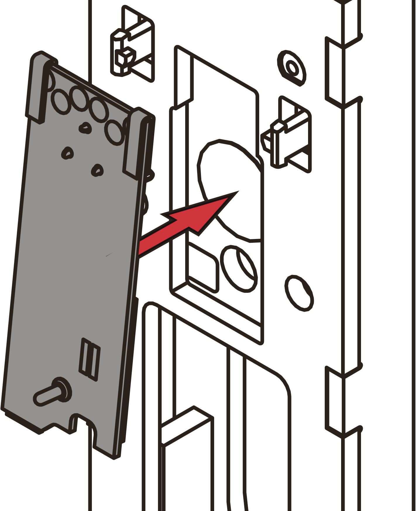
- Push the LockNode as far as it will go in the direction of the arrow.
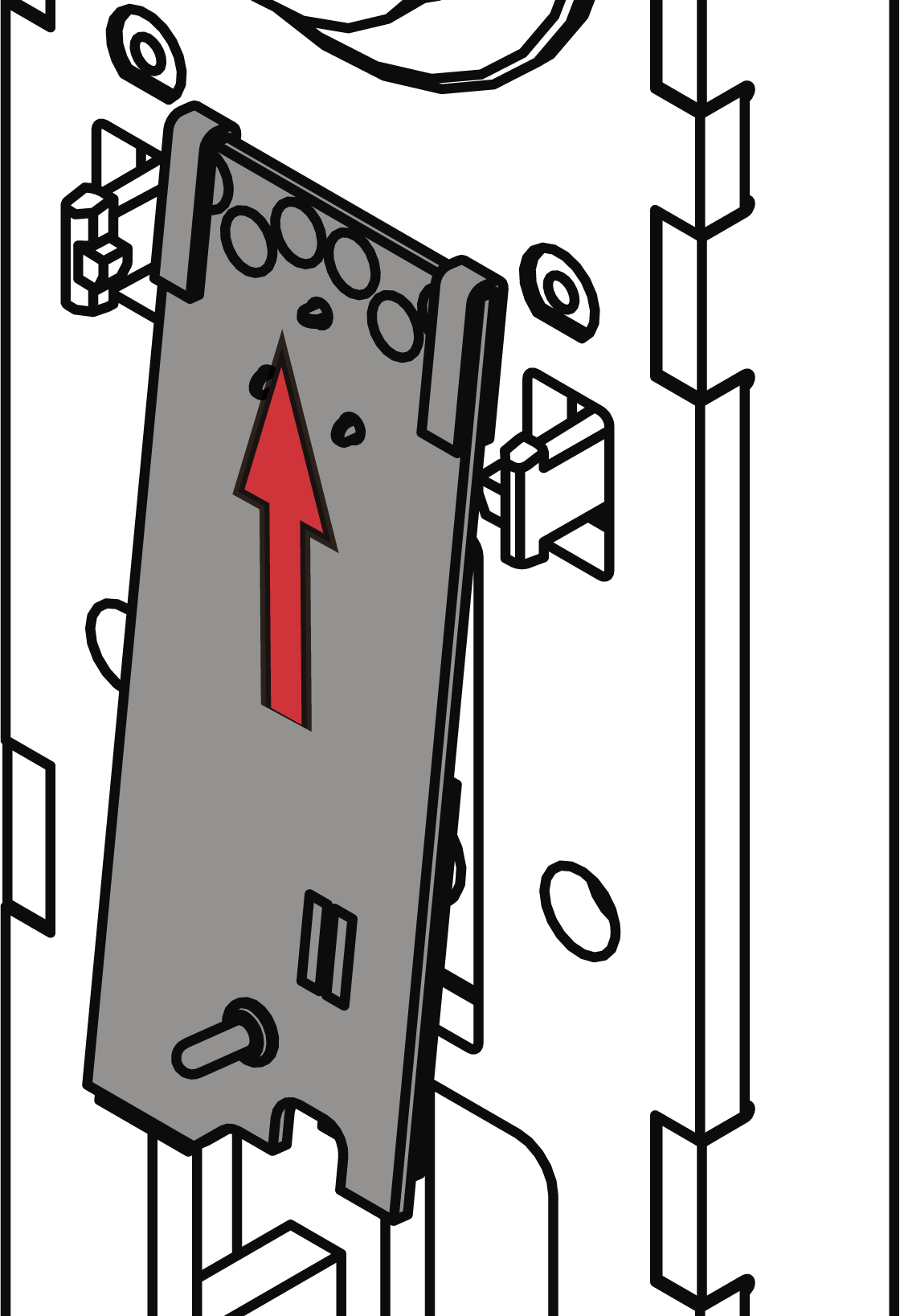
- LockNode lies flat on the subassembly.
- Connect the connecting cable of the LockNode with the connecting cable of the SmartHandle.
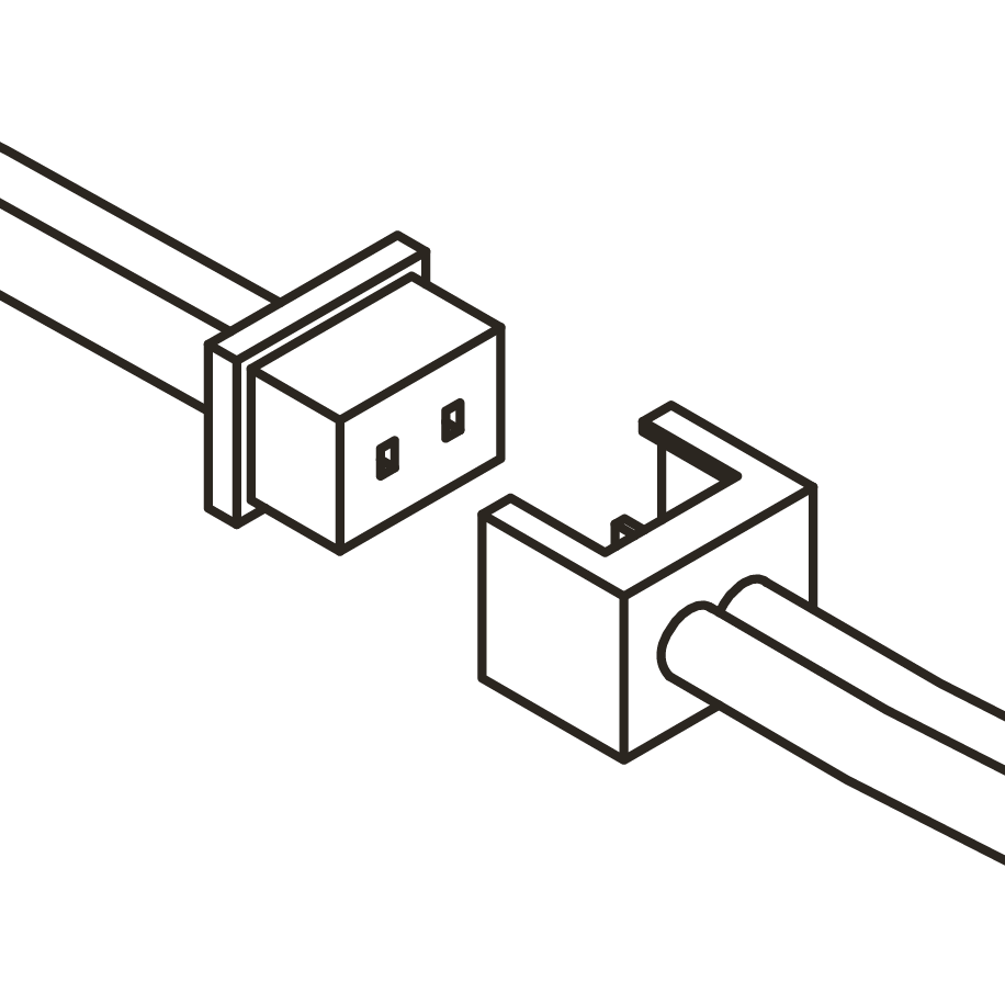
- SmartHandle beeps and flashes red 4 times.
- Store excess connection cable in the SmartHandle subassembly.
IMPORTANT
Malfunction due to weather influences
Even in the WP version, the plug connections are not splash-proof. If moisture reaches the contacts, data transmission may be disturbed.
- Store the cable connectors in the inside area of the SmartHandle.
- Replace the cover and inlay of the SmartHandle (see Quick Start Guide or SmartHandle Manual).
The gold-coloured metal clip on the LockNode connects the LockNode mechanically and electrically (positive pole) with the SmartHandle. When you have mounted the cover and inlay again, the spring-loaded metal pin contacts the inlay (the inlay then acts as an antenna).