Conventional fastening system, including Swiss Round MO: - SmartHandle 3062
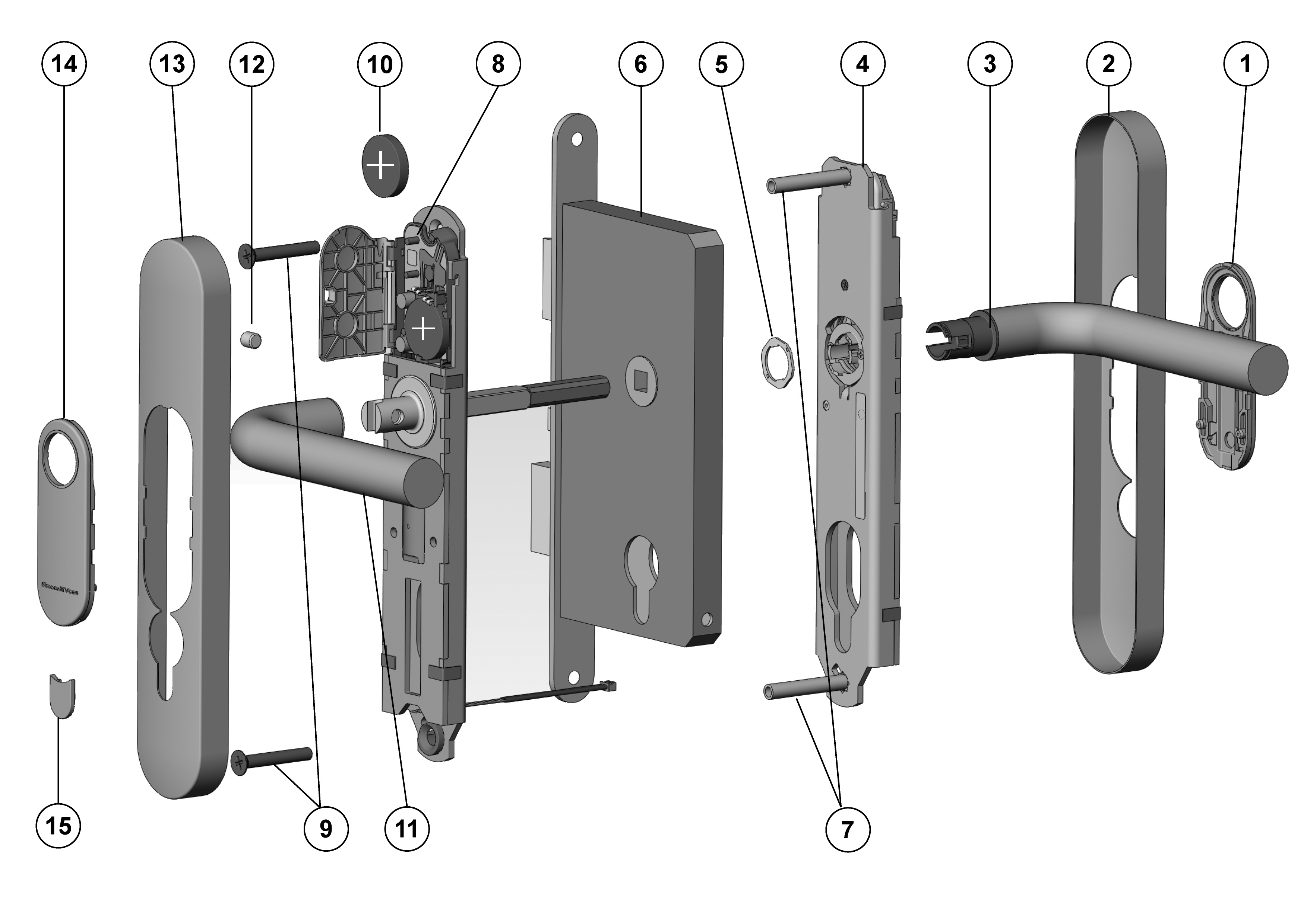
Keys:
- Inlay
- Inlay
- Outer handle, including lock ring
- Outer fitting
- Lock ring
- Door lock (not included in the scope of supply)
- Spacing bolt
- Inside fitting
- Screws
- Upper battery
- Inside handle, including hexagon socket screw
- Inside hexagon screw
- Inlay
- Inlay
- Cover plate
Installation:
- Optional: handles, escutcheons, fittings and other door furniture fitted to the door are to be removed.
- SmartHandle is partly assembled when supplied; see Disassembly.
- The inlay cannot be fitted on some handles, such as offset handles, when they are already installed. Push the inlay onto the outer handle with the logo facing outwards in such cases. You can do this with most handles.
- Optional: In a lock with an 8.5 mm or 10 mm spindle, push the corresponding sleeve (8 mm --> 8.5 mm [not included in the supply package] or 8 mm --> 10 mm) through the retainer opening in the mortise lock from the inside.
- Push the inside fitting (8) spindle through the retainer slot in the door's mortise lock (6), so that the fitting is flush with the door. Ensure that you do not squash the 3-pole cable when doing so.
- Position the inside fitting (8) in such a way that it is parallel to the door.
- Mark the drill holes required on the door through the corresponding holes in the inside fitting (8).
- Remove inside fitting (8) from the door.
- Drill the holes with a diameter of 8 mm (top hole) and 13 mm (lower hole) through the door.
- Push inlay (1) onto the outer handle (3). Depending on the handle model, it may not be possible to fit it once the handle is installed.
- Insert outer handle (3) horizontally into the outer fitting (4) until it will go no further, placing it in the direction that you require, depending on whether it is a DIN left-hand or right-hand door.
- Place handle fastener piece (5) into position (see Figures 2 and 3).
- Hold the outside handle (3) and use the spanner to rotate the handle fastener piece (5) about 75° to the right until it fits into position (Figures 4 and 5). If you do not fit it correctly, the handle may come loose again.
- The inside fitting (8) is mounted onto the inner surface of the door. Push the inside fitting spindle through the retainer slot in the mortise lock and push the inside fitting onto the door until it is about 5 cm away.
- Push the 3-pole cable for the inside fitting through the lower hole (13 mm in diameter) and ensure that it doesn't get caught or buckled.
- Push inside fitting (8) through the door completely, so that it is flush with the door. In doing so, place the cable escutcheon into the lower drill hole.
- The outer fitting (4) is mounted from the outer side of the door.
- Insert the lower spacing bolt (7) into the outer fitting (4); the upper spacing bolt (7) is pre-fastened into position in the factory.
- Push the outer fitting retainer slot onto the spindle while pushing the two spacing bolts (7) through the drill holes up to a gap of 2 cm.
- Insert the 3-pole cable through the cut-out in the lower end of the outer fitting.
- Push the outer fitting (4) onto the door completely. In doing so, ensure that the inside fitting cable does not get caught or buckled.
- Connect the 3-pole cable from the inside fitting to the 3-pole cable from the outer fitting. This cable can only be inserted in one direction. Do not pull on the cables while doing so; just carefully secure the plug-in connection into position.
- The 2-pole cable from the outer fitting can hang freely, but must not get caught when the outer cover (2) is fitted. Do not pull on the cable.
- Press outer and inside fittings together, so that they are both flush against the door.
- Press the electronics module cover lid in the inside fitting (8) carefully out of its bracket and fold back horizontally. Make sure that the electronics are not exposed to mechanical load and are not damaged in any other way.
- Carefully remove the upper battery (10) from the holder. Use clean gloves free of fat or grease to handle batteries.
- Insert the supplied screws (9) through drill holes in the inside fitting (8) from inside the door and fasten to the spacing bolts (7) on the outer fitting by hand, using about 5-7 Nm.
- Insert the upper battery (10) with the positive terminals facing away from the door into the brackets; in doing so, insert the batteries under the black retaining collar first. Use clean gloves free of fat or grease to handle batteries.
- Lock the electronics cover lid back into place.
- Check that the outer handle (3) can turn easily; if it does not, there may be a problem with the mortise lock (6) or the handle may have been fitted incorrectly. In case of doubt, disassemble components and start again from Step 10.
- Push the cylinder through the designated hole in the fitting from the outside. In doing so, ensure that the cam is at the six o'clock position and that the 3-pole cable does not get caught or buckled.
- Fasten the cylinder with the fastening screw by hand, using about 5-7 Nm – note that cylinder and screw are not part of the supply.
- Carefully push the 3-pole cable into the outer fitting.
- Push inlay (14) onto the inside handle (11). Depending on the handle model, it may not be possible to fit it once the handle is installed.
- Push inside handle (11) onto the inside fitting (8) fastening flange until it will go no further.
- Fasten the hexagon screw (12) on the inside handle (11) firmly by hand.
- Push the cover (13) over the inside handle (11).
- Carefully push the inlay (14) through the opening in the inside cover (13).
- Push cover (13) onto the inside fitting (8), so that it is flush with the door. The cover is not symmetrical; look carefully at the marking to ensure correct positioning (Diagram 7).
- Click the inlay (14) carefully into the cover (13).
- Press the cover plate (15) for the cylinder body carefully into the opening in the inside cover (13).
- Push the cover (2) over the outside handle (3).
- Carefully push the inlay (1) through the opening in the outside cover (2).
- Push cover (2) onto the outer fitting (4), so that it is flush with the door. The cover is not symmetrical; look carefully at the marking to ensure correct positioning (Diagram 7).
- Click the inlay (1) carefully into the cover (2).