Installing the fitting - Digital SmartHandle AX
- Door pre-drilled.
- PH2 screwdriver at hand.
- TX15 screwdriver at hand.
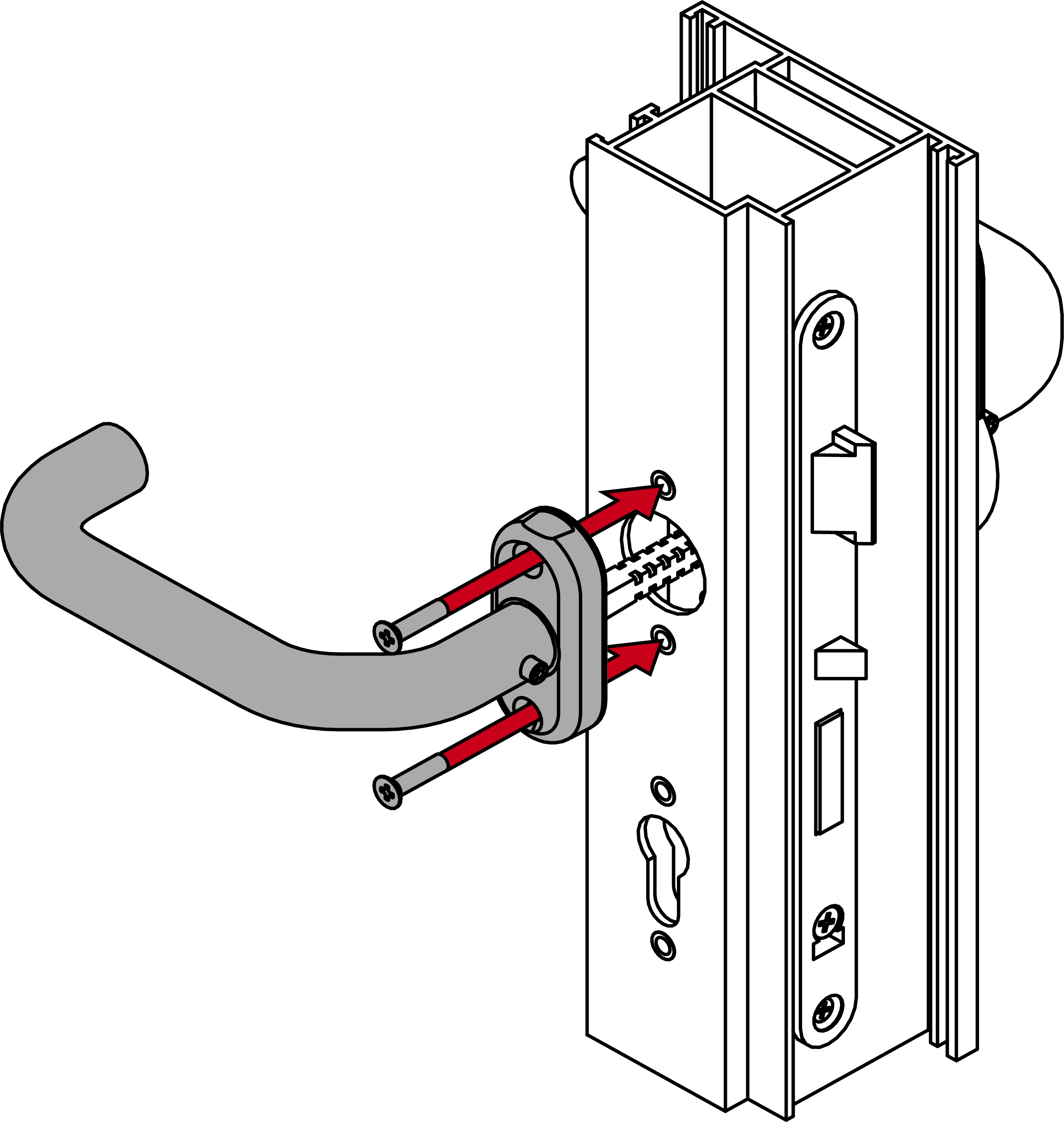
- Insert the supplied blind rivet nuts into the door frame.
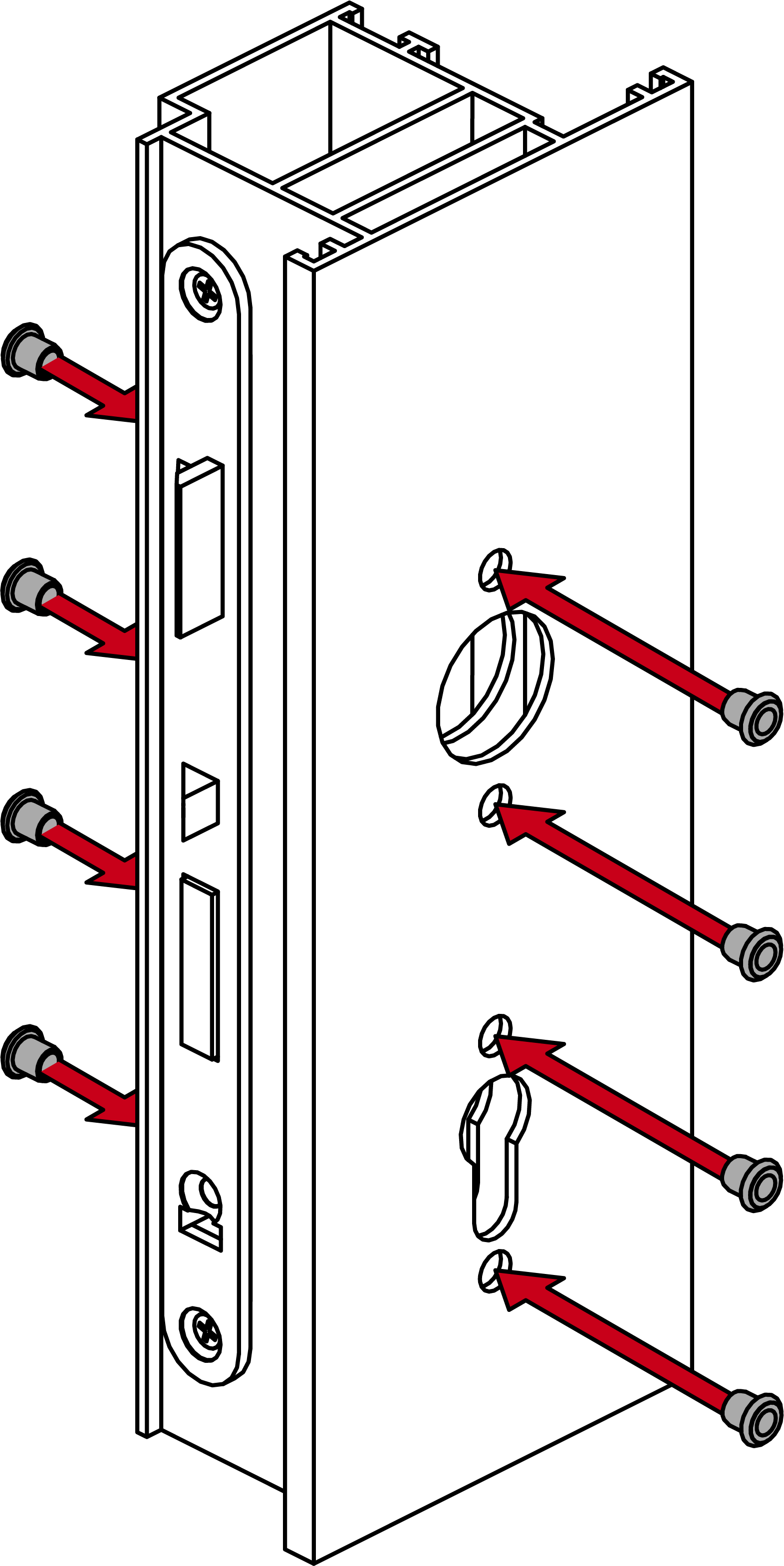
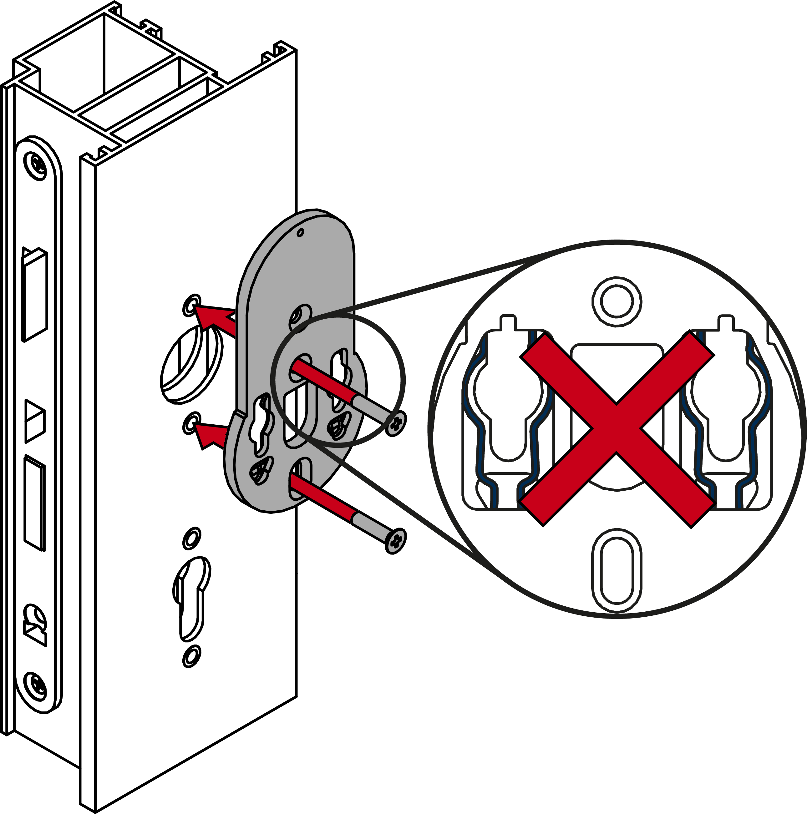
- Screw the mounting plate firmly into place on the outside so that the spring clips are facing the door (PH2, torque 1.1 Nm).
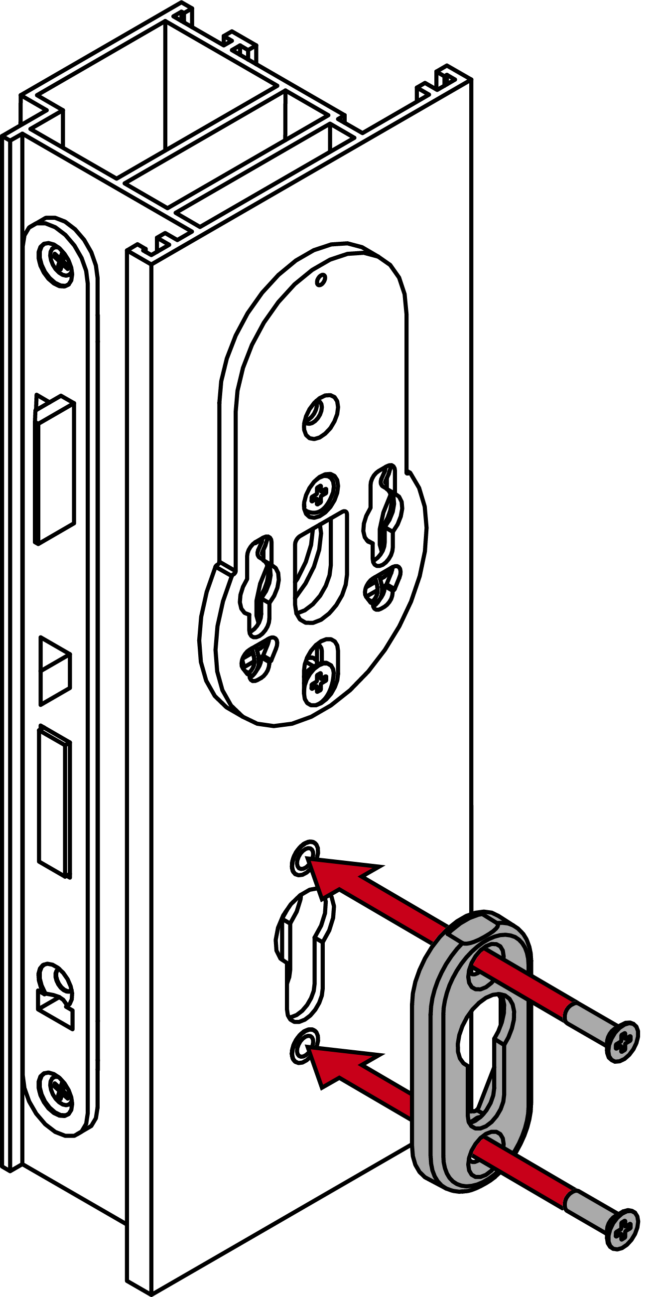
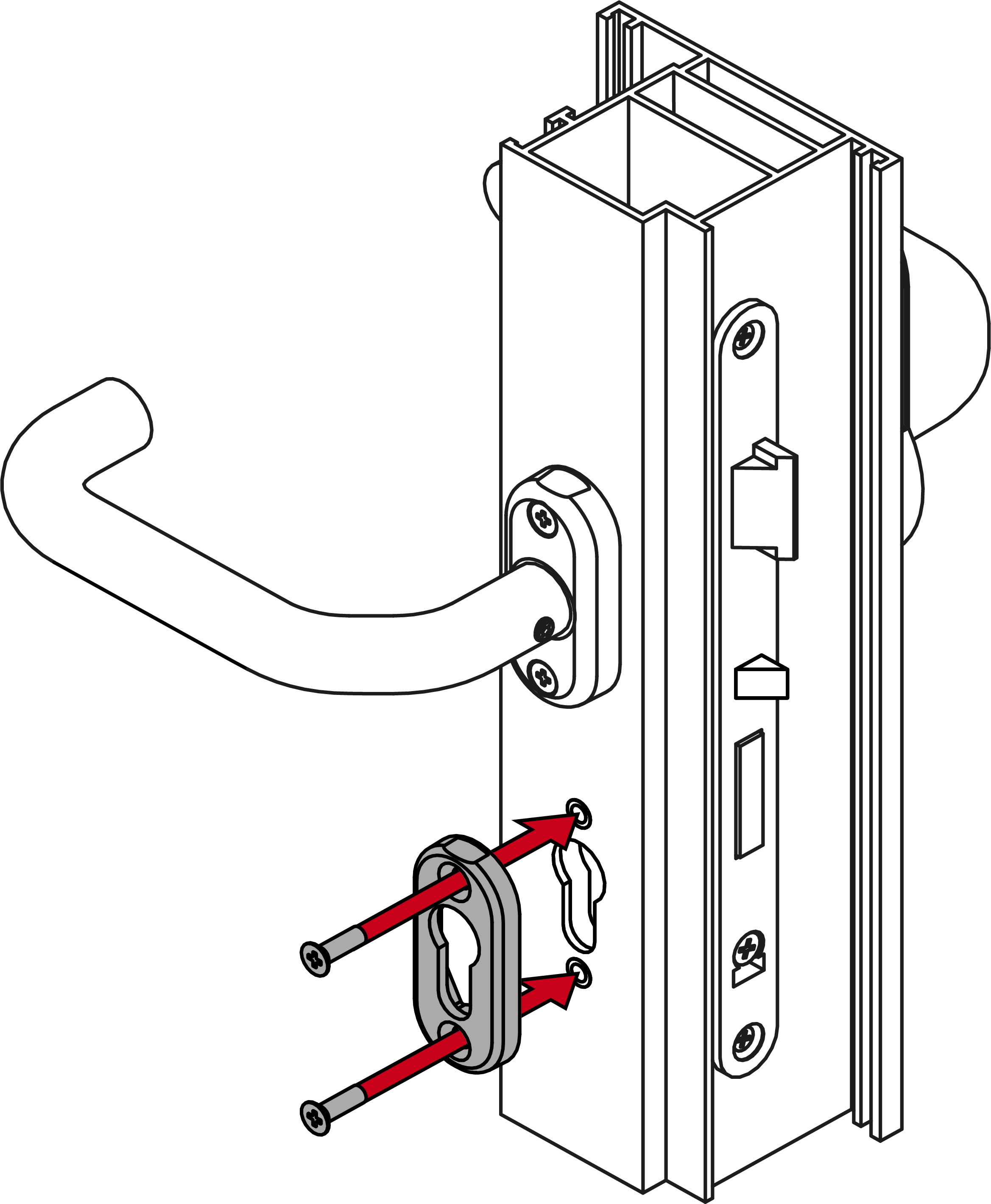
- Screw the escutcheon base firmly to the outside (PH2, torque 1.1 Nm).
- Screw the escutcheon base firmly into place on the inside (PH2, torque 1.1 Nm).
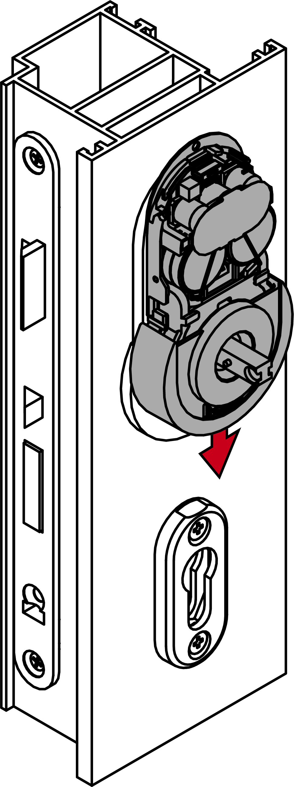
- Insert the fitting into the mounts on the mounting plate.
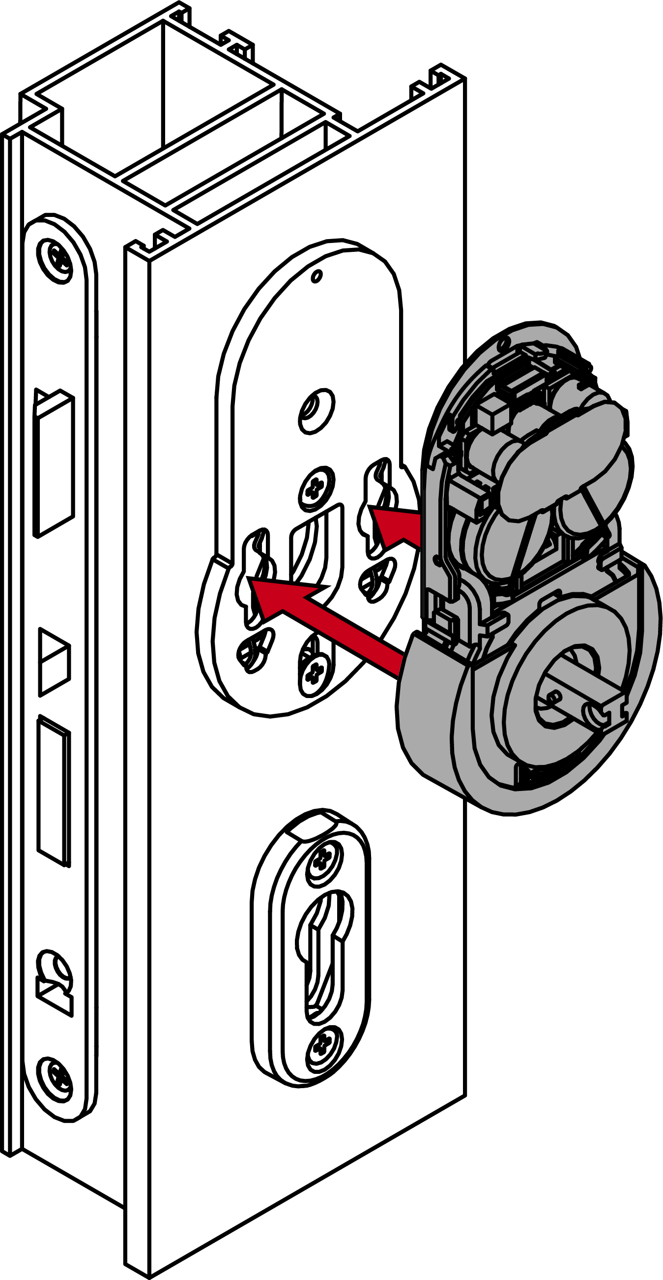
- Push the fitting into the mounting plate until it locks into position.
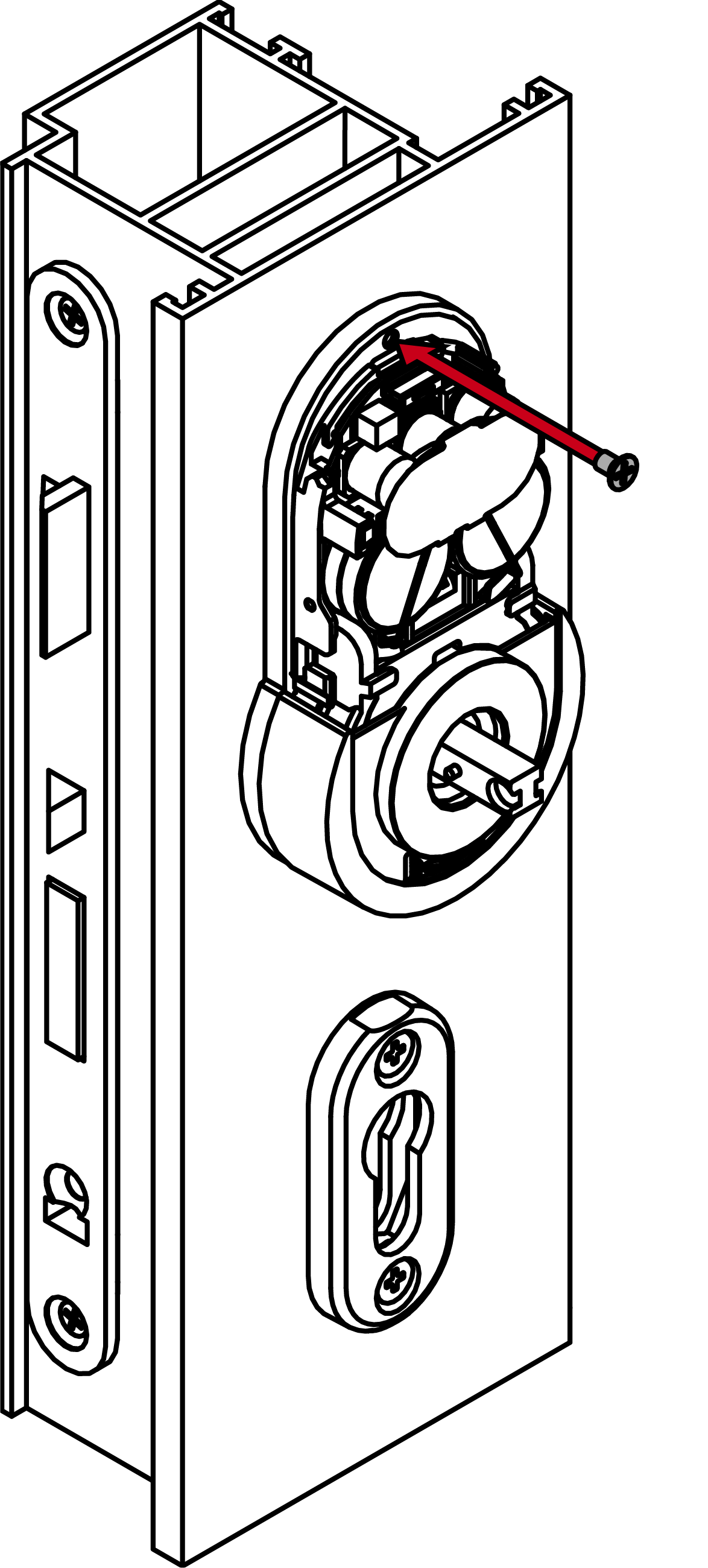
- Screw the fitting firmly to the mounting plate (PH1, torque 0.8 Nm).
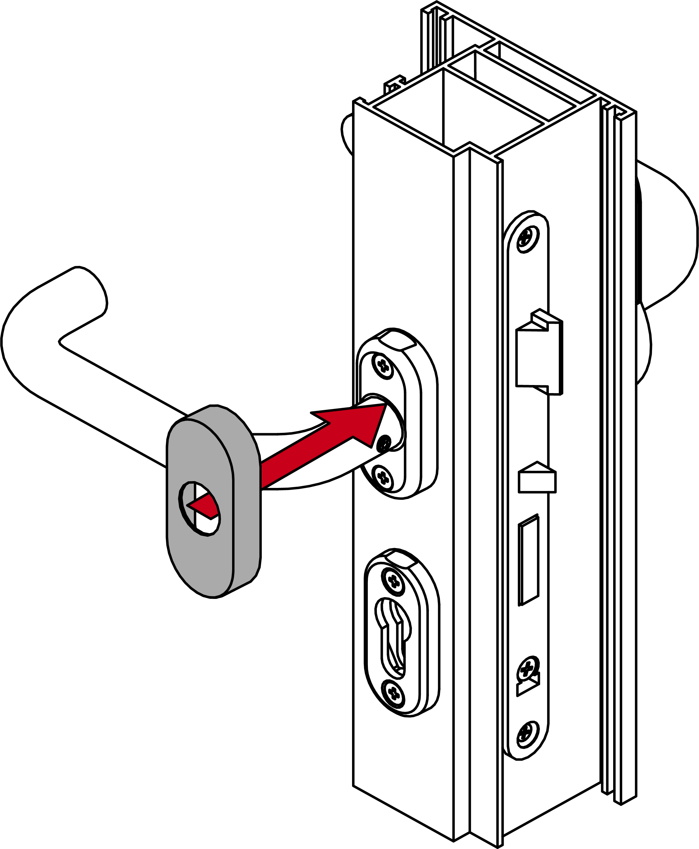
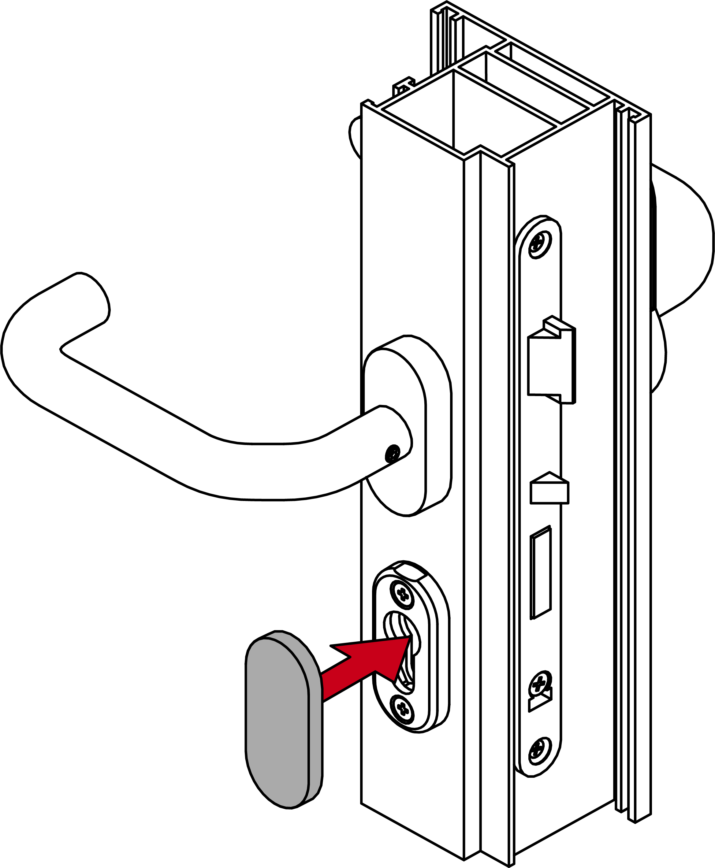
- Place a cover with the notch facing downwards on the escutcheon base.
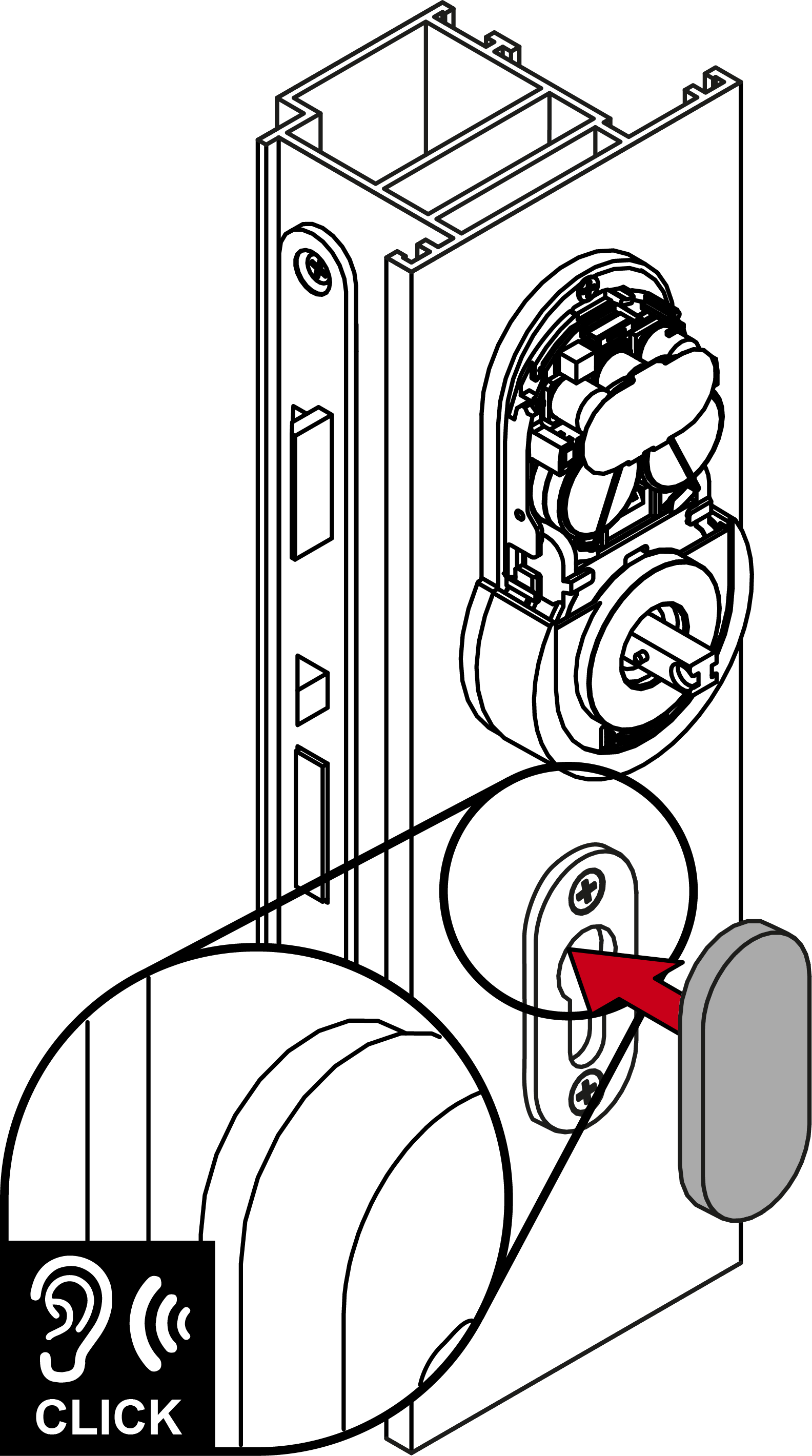
- Place the cover on the fitting.
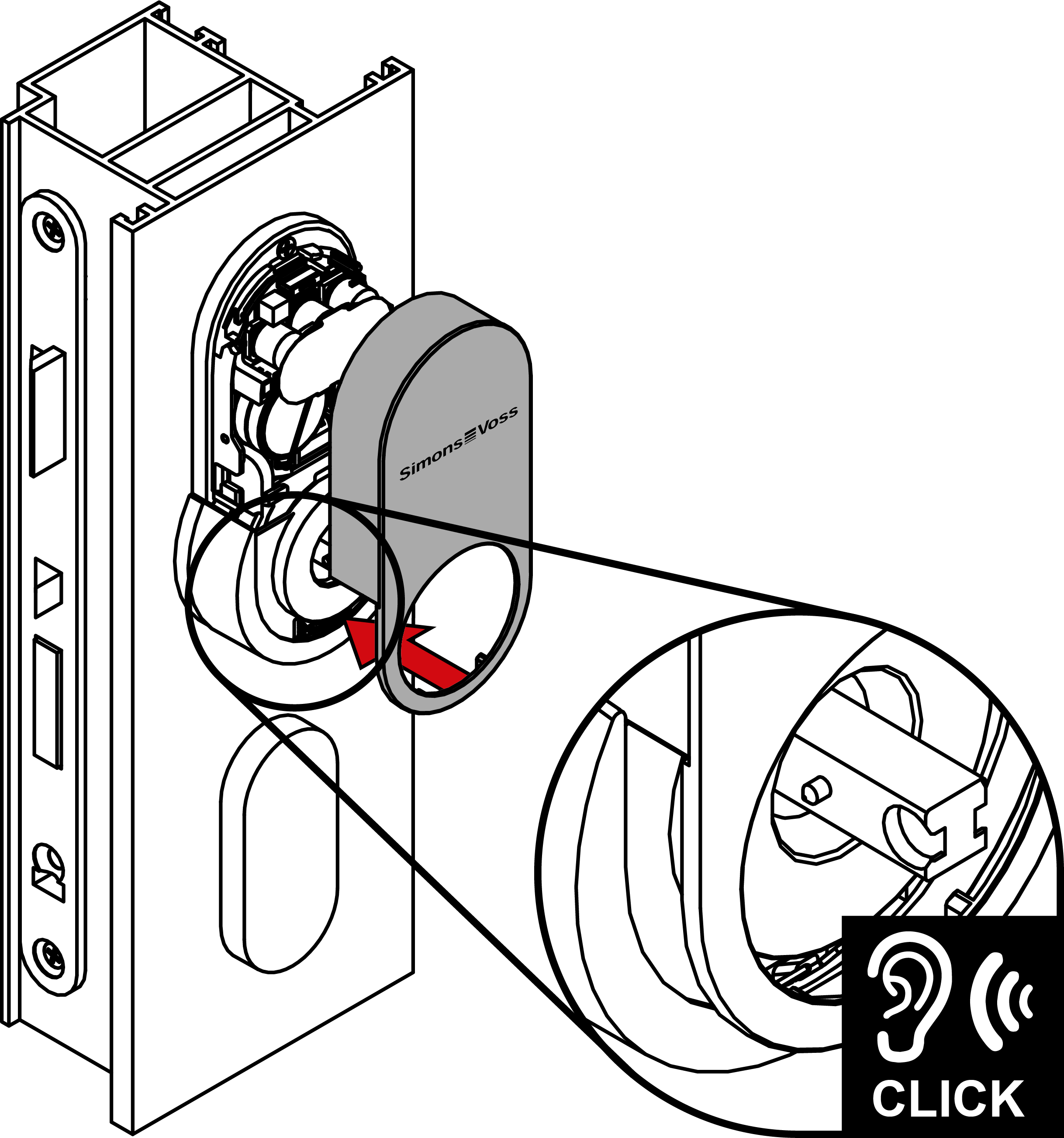
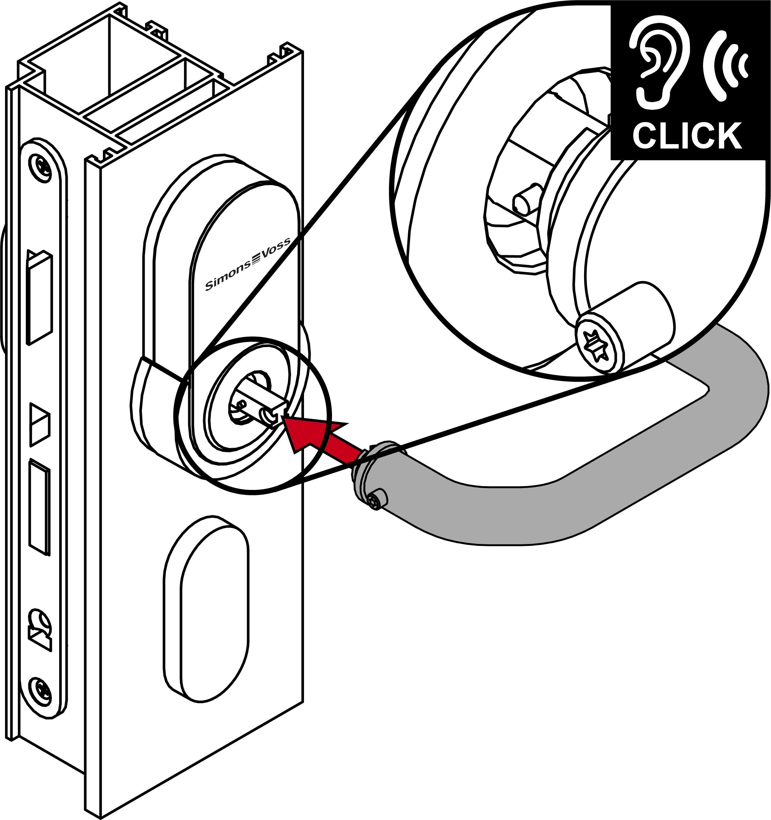
- Fit the outside handle into position on the fitting.
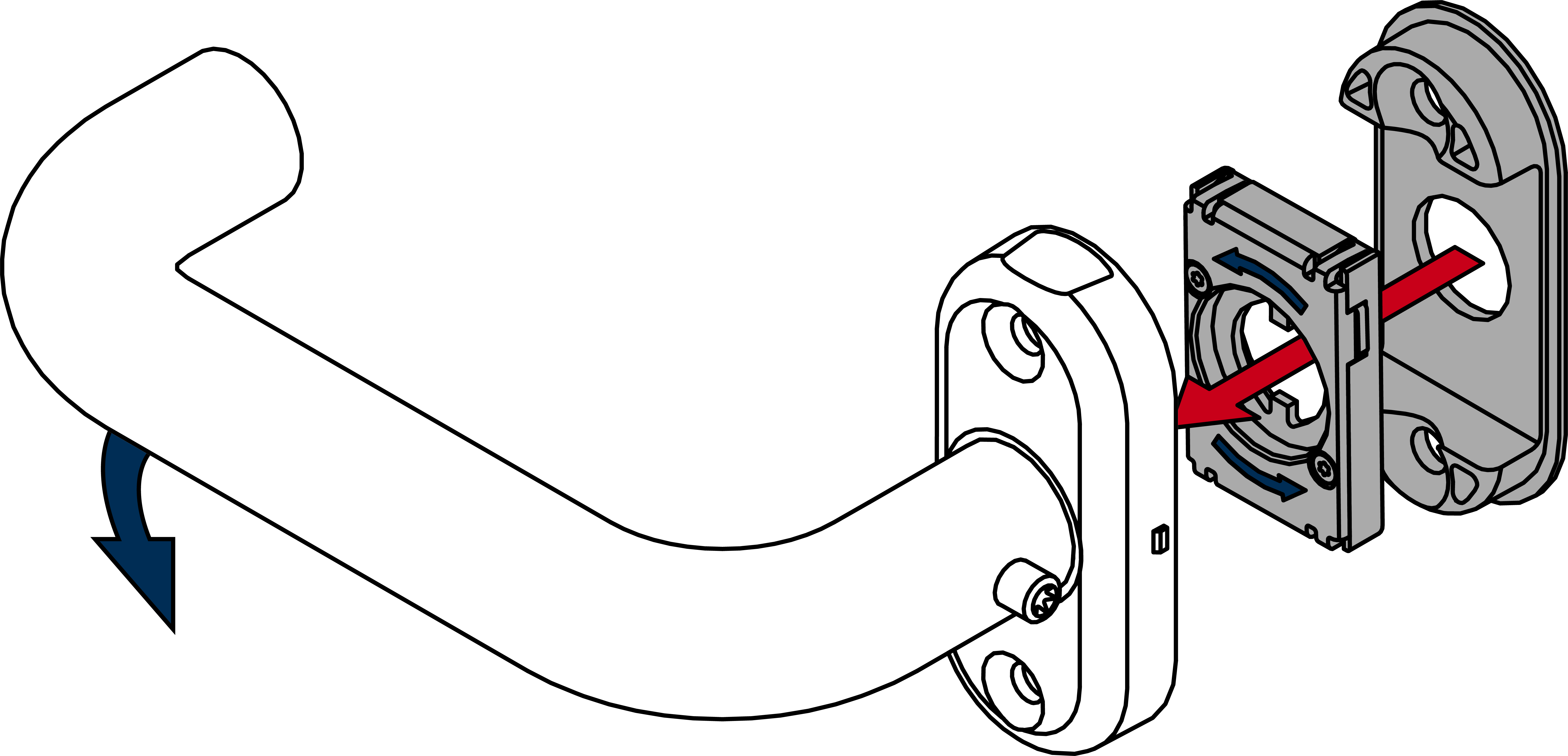
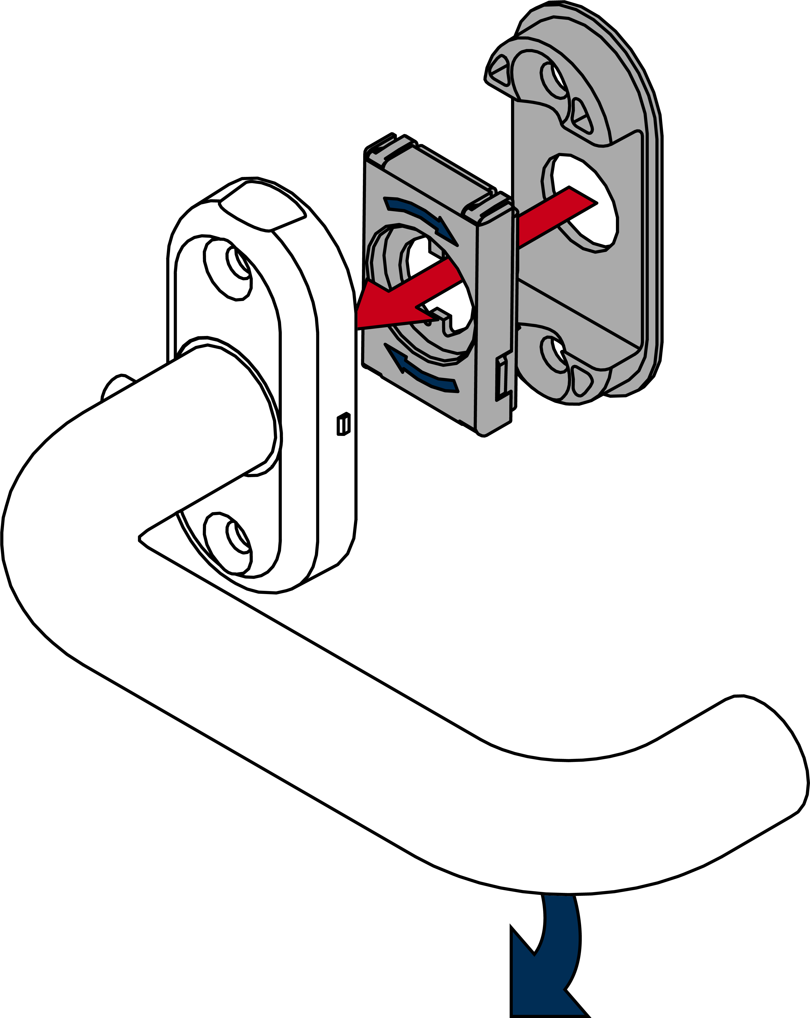
- Determine the required direction of rotation for your inner handle.
- Insert the spring element appropriately.
- Place the underlay in the inner handle unit.
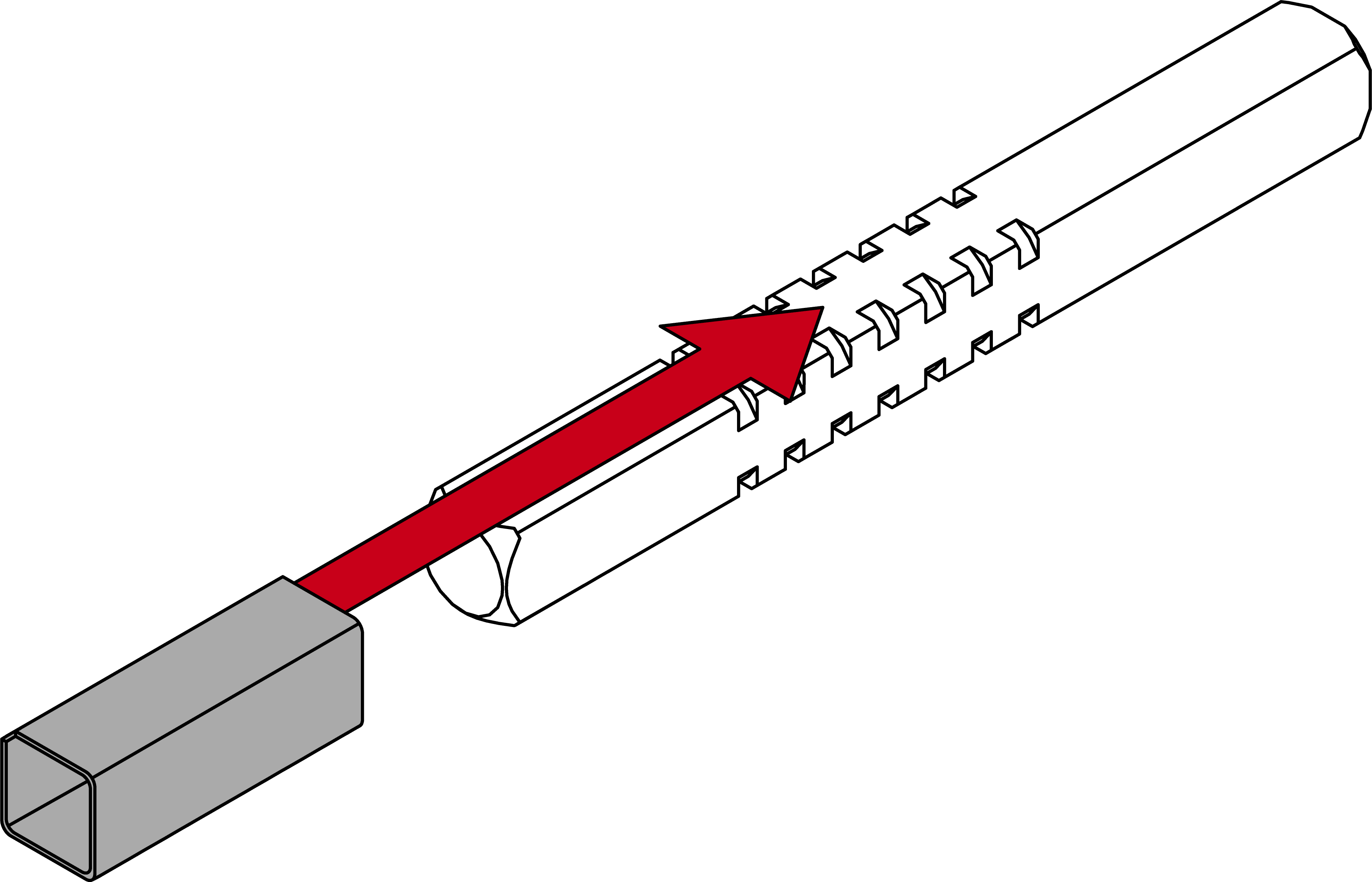
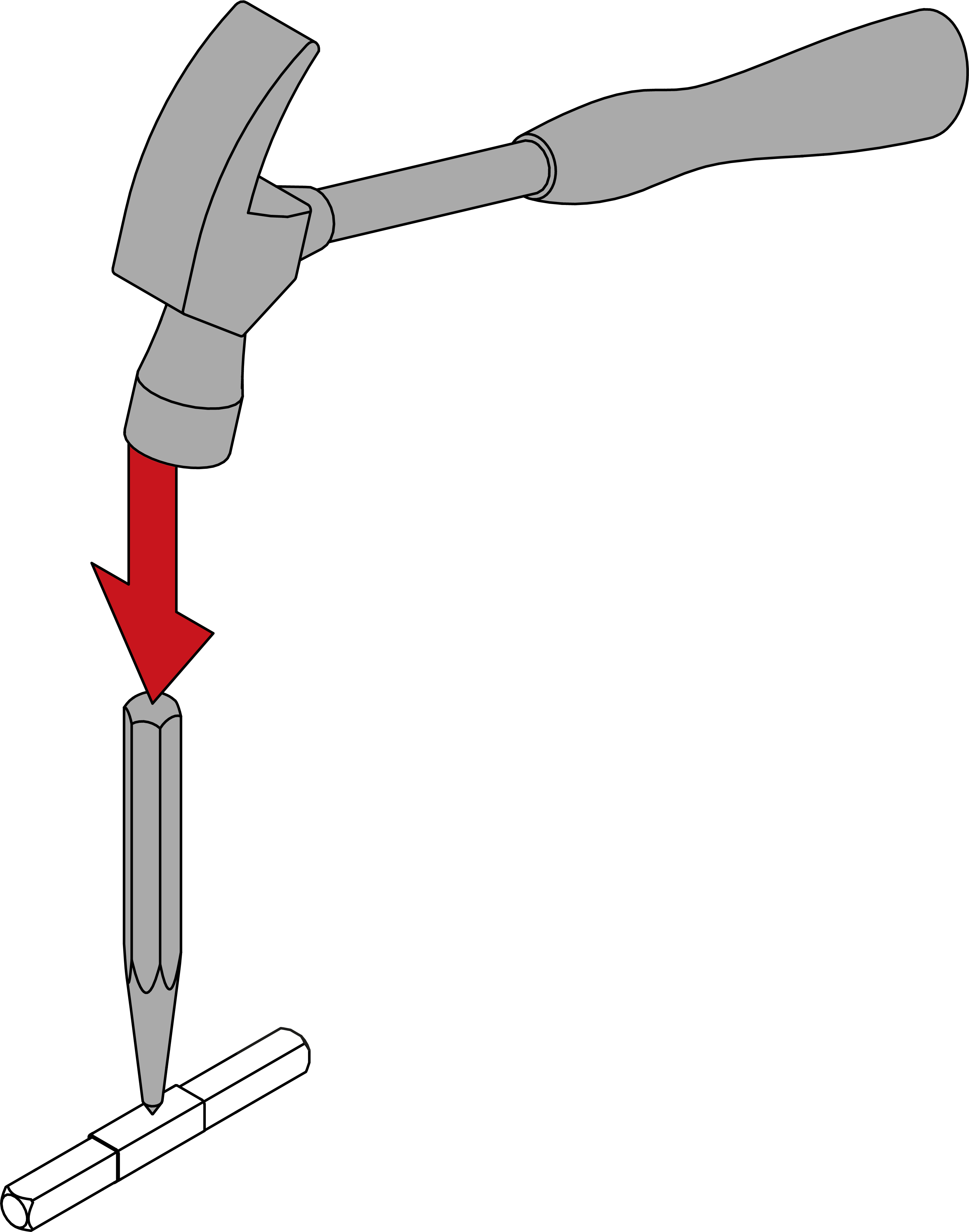
- For 8.5 mm and 10 mm spindle: slide the adapter sleeve into the centre of the spindle. Use a punch and hammer to make an indent in the adapter sleeve to prevent it from slipping.
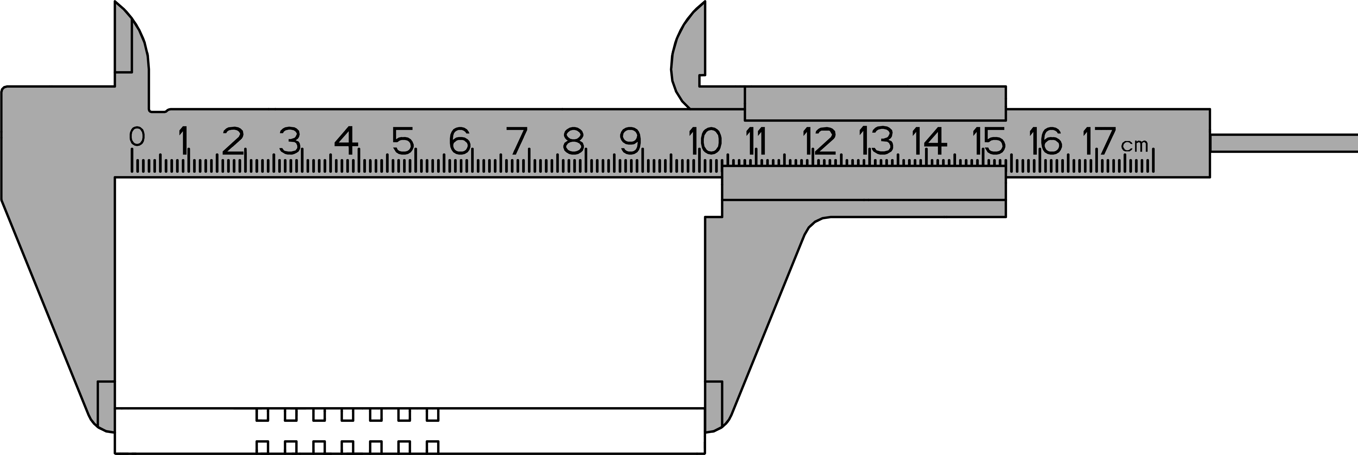
- Measure the total length of the spindle.
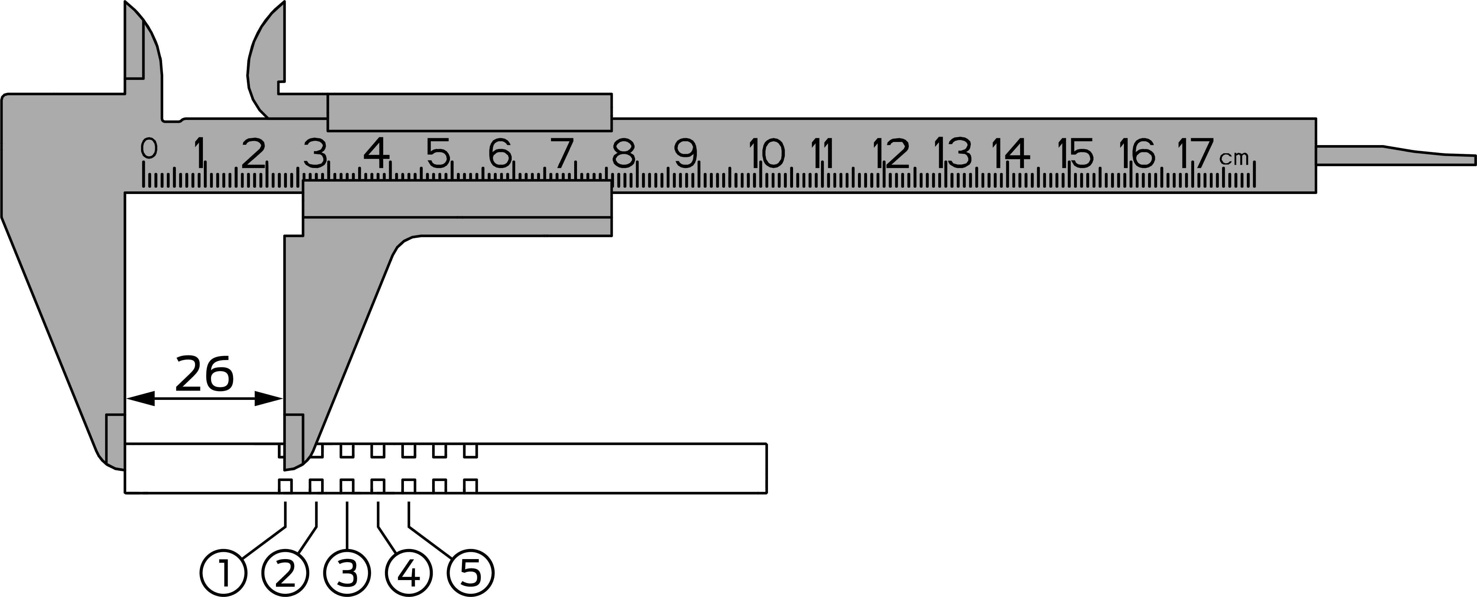
- Locate the inside of the spindle (four-edge end up to the centre of the first groove = 26 mm).
- Use the table to determine the position of the O-ring.
Area
Door thickness (mm)
Spindle length (mm)
Ring position
S
40 - 42
94
3
S
40 - 42
104
5
S
43 - 47
94
2
S
43 - 47
104
4
S
48 - 52
94
1
S
48 - 52
104
3
S
53 - 57
104
2
S
58 - 61
104
1
M
60 - 62
114
3
M
60 - 62
124
5
M
63 - 67
114
2
M
63 - 67
124
4
M
68 - 72
114
1
M
68 - 72
124
3
M
73 - 77
124
2
M
78 - 81
124
1
L
80 - 82
134
3
L
80 - 82
144
5
L
83 - 87
134
2
L
83 - 87
144
4
L
88 - 92
134
1
L
88 - 92
144
3
L
93 - 97
144
2
L
98 - 101
144
1
XL
100 - 184
O-ring is 30–35 mm from the cut end of the spindle.
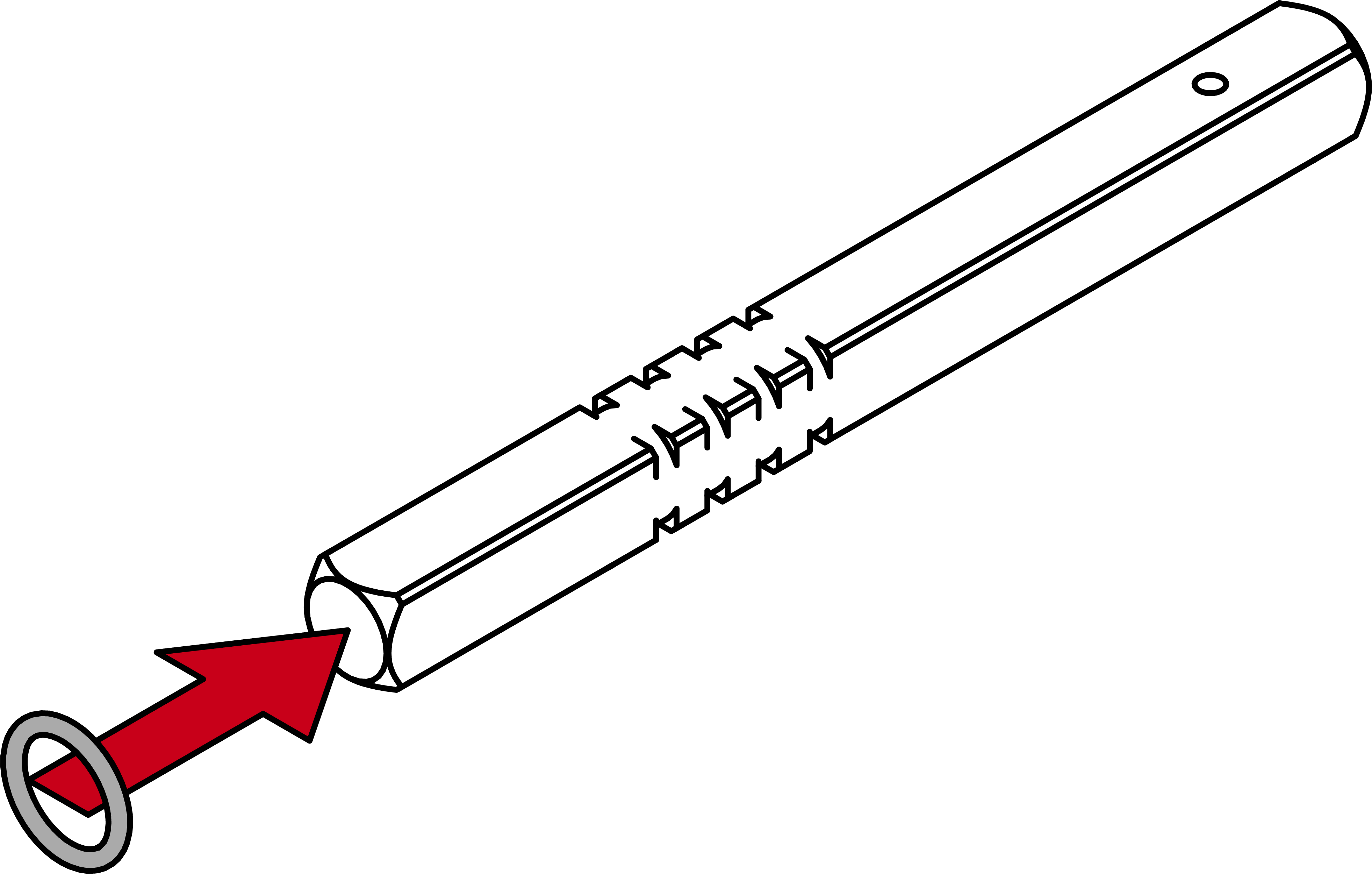
- Slide the O-ring onto the calculated groove.
- Insert the spindle into the door with the ring-free side as far as it will go.
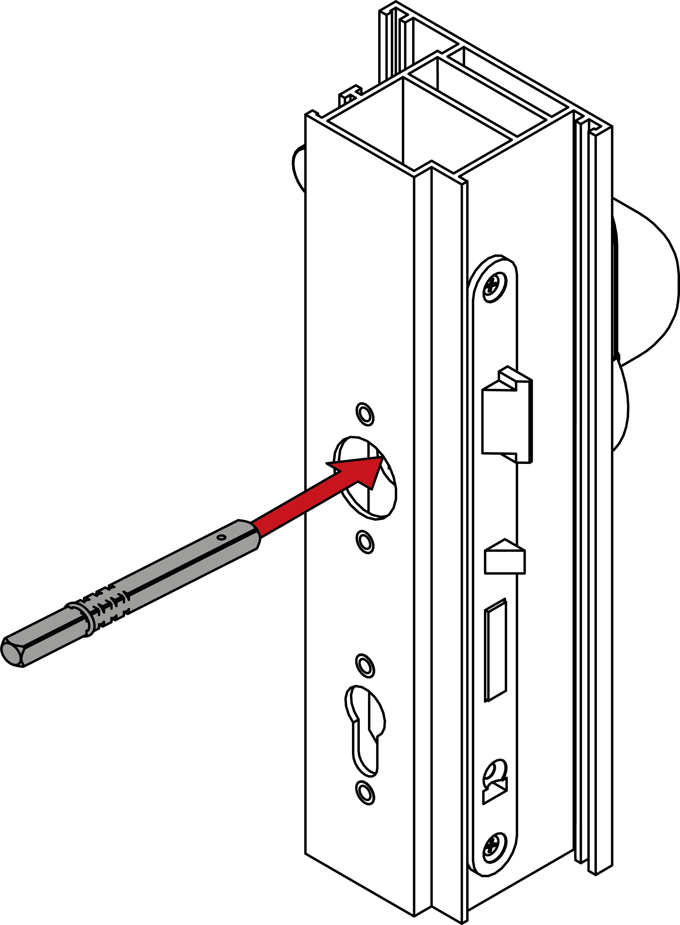
- For FH: insert the dummy cylinder.
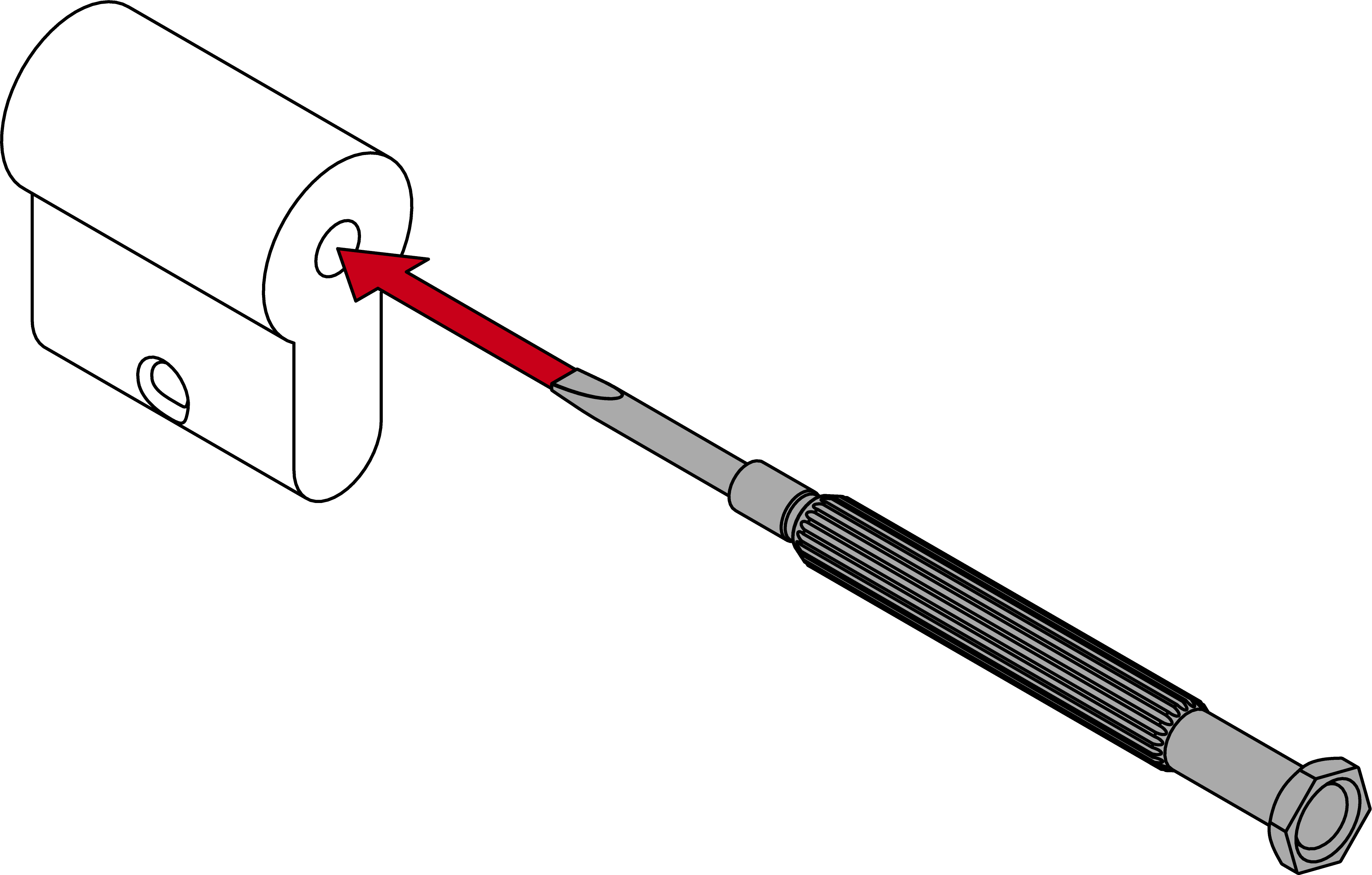
NOTE

Feed the blank cylinder into the hole using a screwdriver
It is difficult to position the blank cylinder correctly, especially in thick doors.
- Insert a screwdriver into the hole in the blank cylinder.
- Position the blank cylinder using the screwdriver.
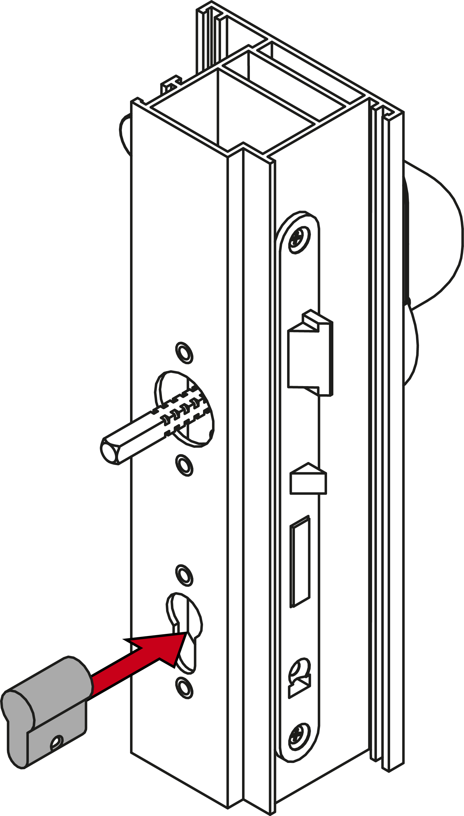
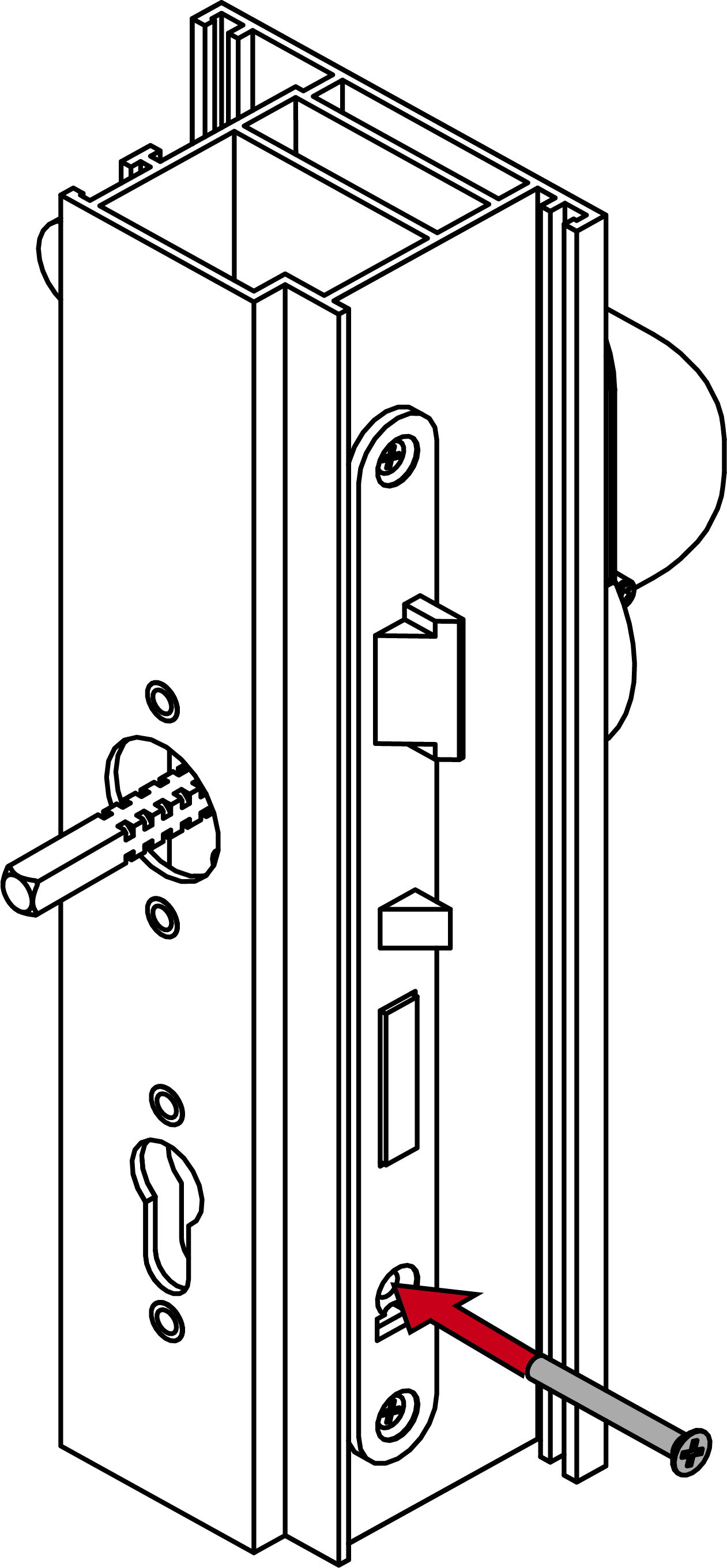
- For FH: screw the dummy cylinder firmly into place (PH2, torque 1.1 Nm).
- Screw the inner handle unit onto the spindle (PH2, torque 1.1 Nm).
- Screw the escutcheon base firmly into place on the inside (PH2, torque 1.1 Nm).
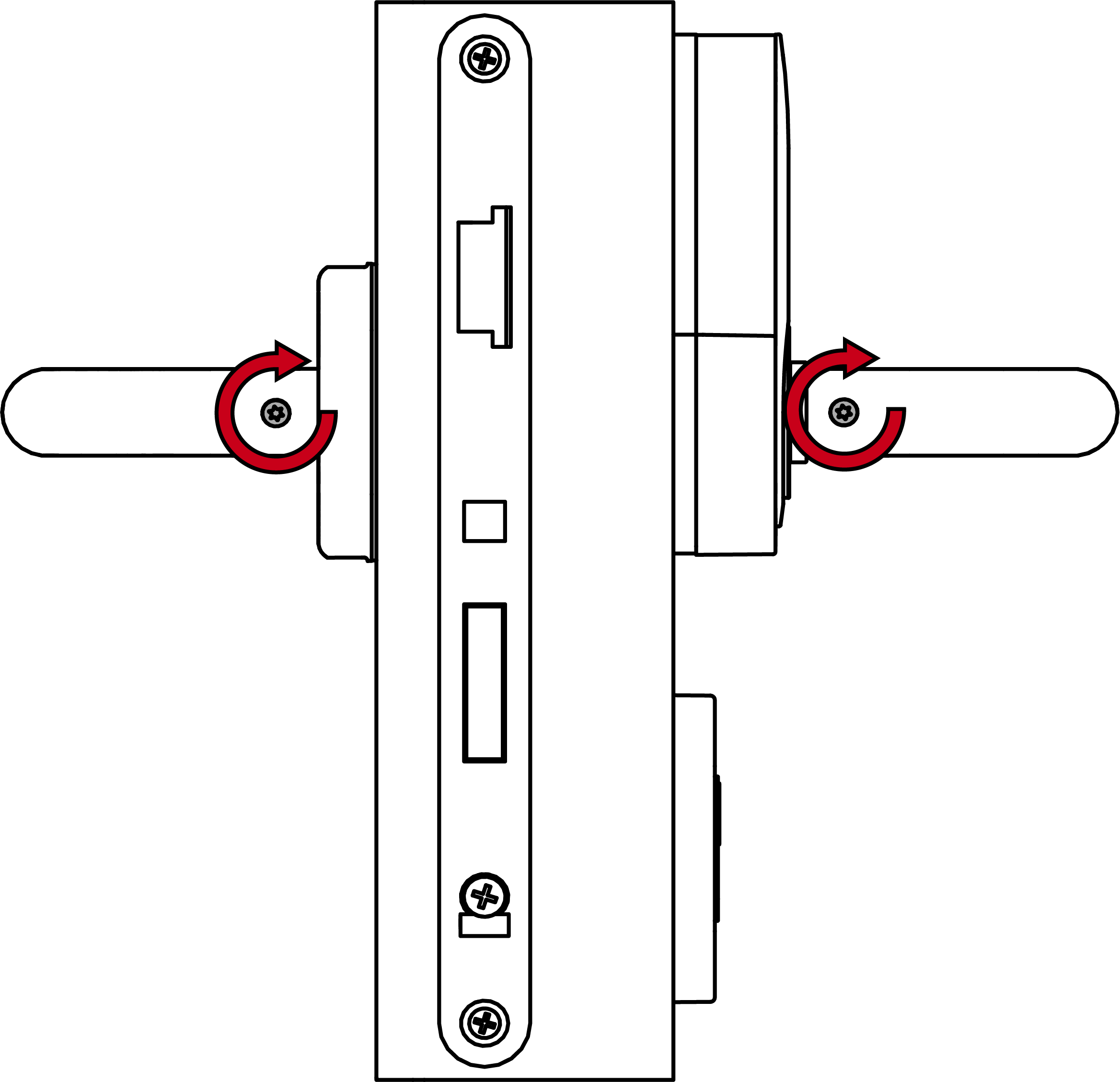
- Fasten the grub screws firmly onto both handles (TX15, torque 5.0 Nm).
- Place the inner handle cover with the notch facing downwards onto the inner handle escutcheon.
- Place a cover with the notch facing downwards on the escutcheon base.
- Fitting is now installed.