Installing the fitting - SmartHandle AX Advanced
- Door pre-drilled.
- PH2 screwdriver at hand.
- TX15 screwdriver at hand.
- Caliper gauge at hand.
- For non-MO: insert the blank cylinder.
NOTE

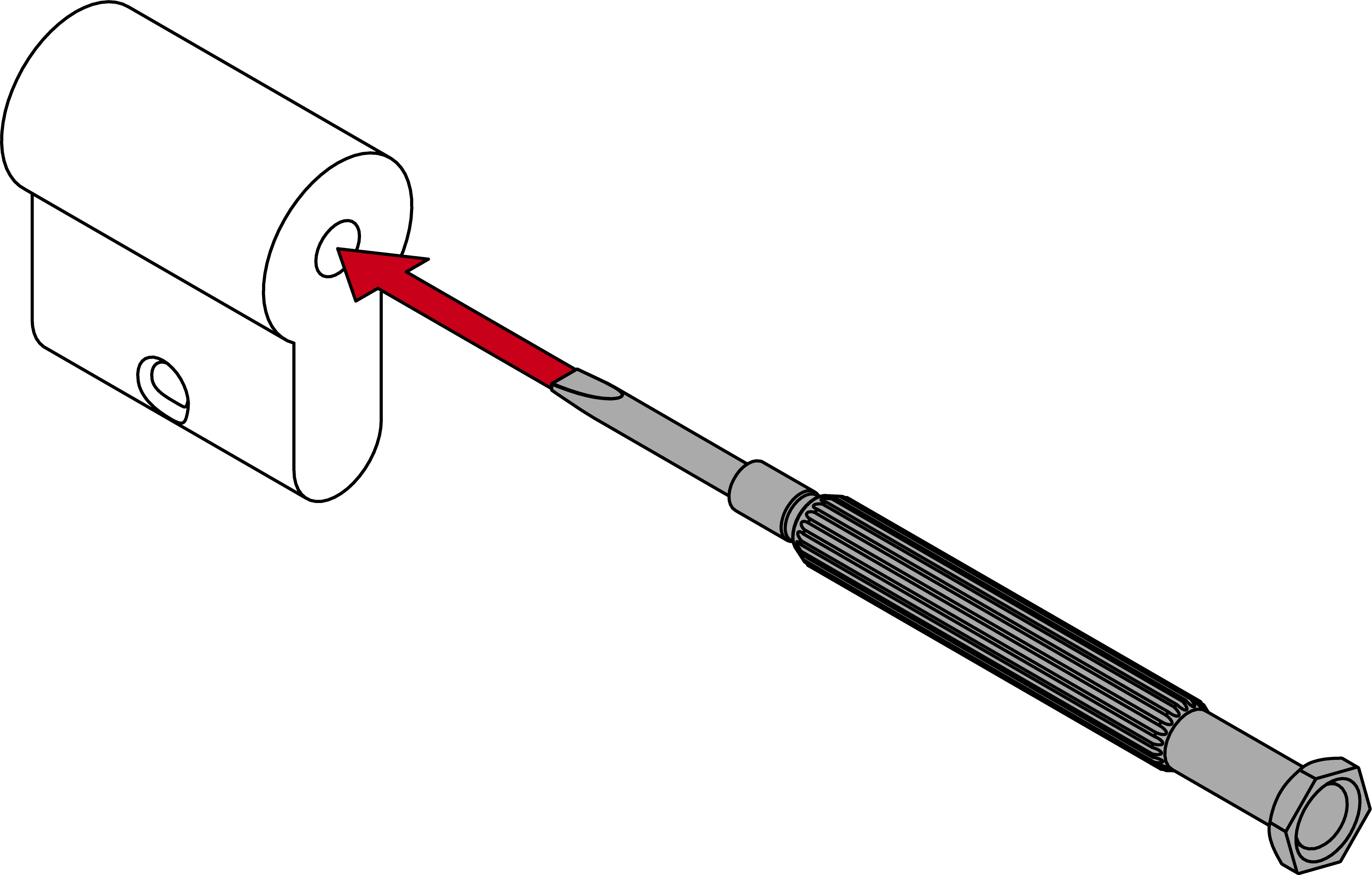
Feed the blank cylinder into the hole using a screwdriver
It is difficult to position the blank cylinder correctly, especially in thick doors.
- Insert a screwdriver into the hole in the blank cylinder.
- Position the blank cylinder using the screwdriver.
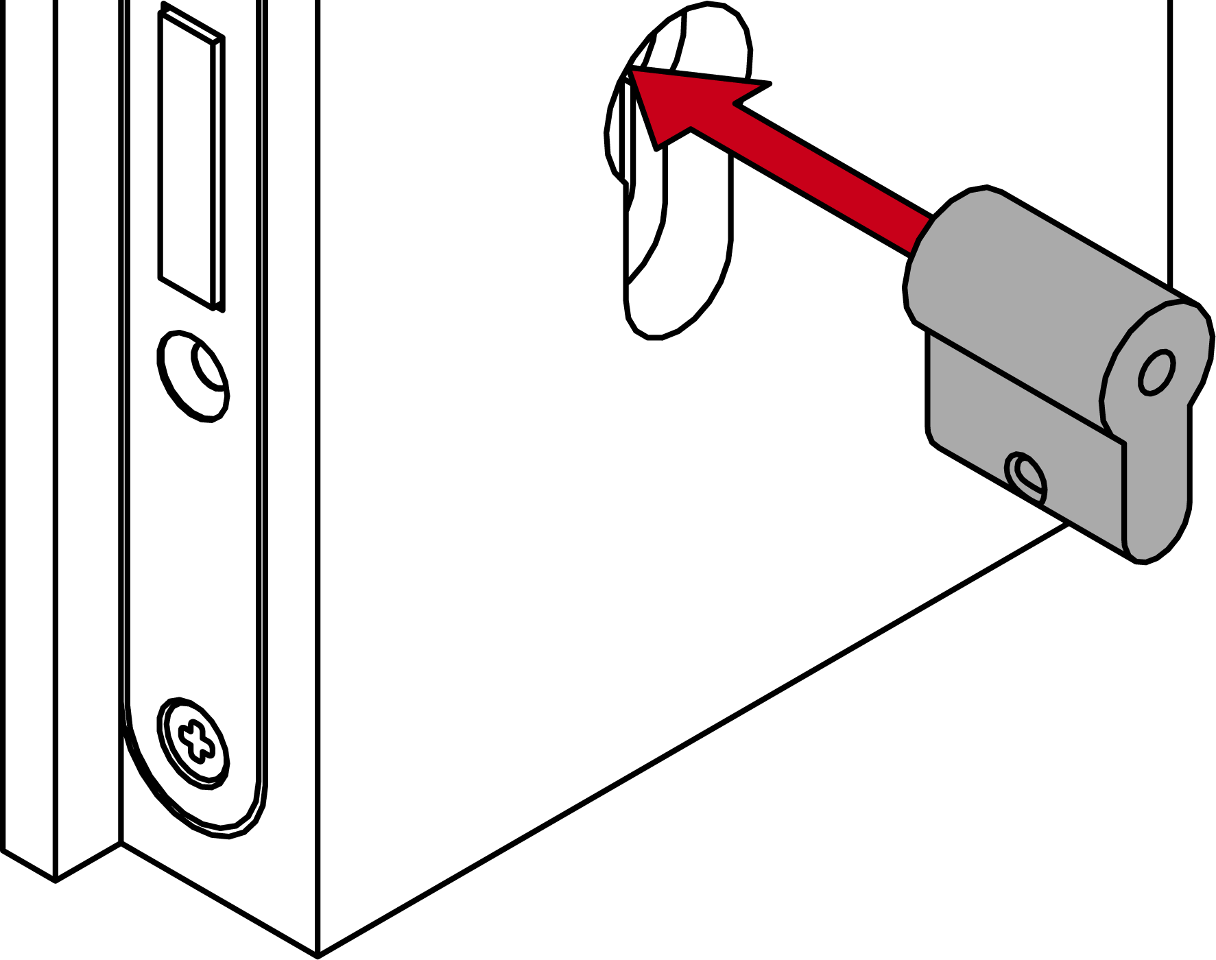
- For non-MO: screw the dummy cylinder firmly into place (PH2; torque: 1.1 Nm).

- When using a short backplate: insert the mounting disc into the smaller fastening plate.
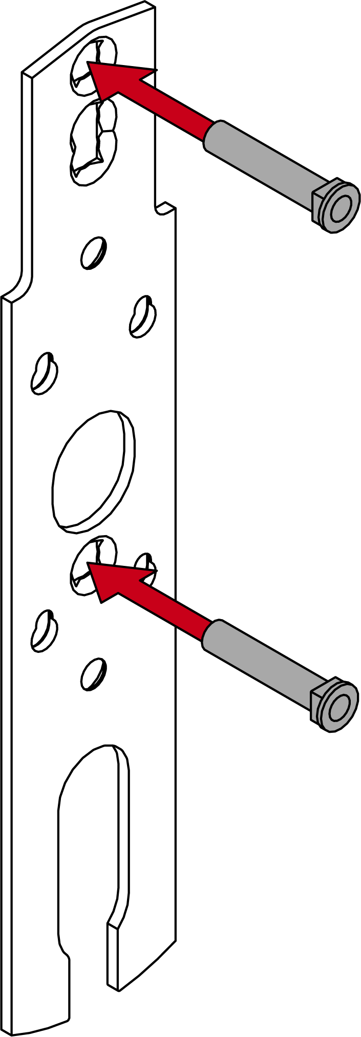
- Insert the sleeve nuts into the smaller fastening plate (long backplate: middle/top; short backplate: middle/bottom).


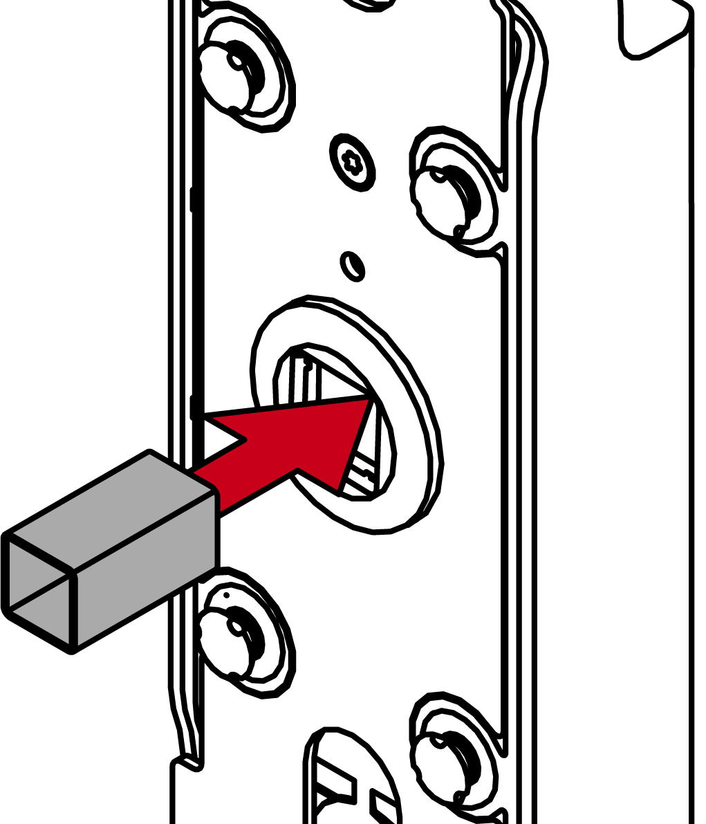
- For 7 mm spindle: Insert the adapter shoe into the spindle mount on the module support.
- Insert the module support into the fastening plate.
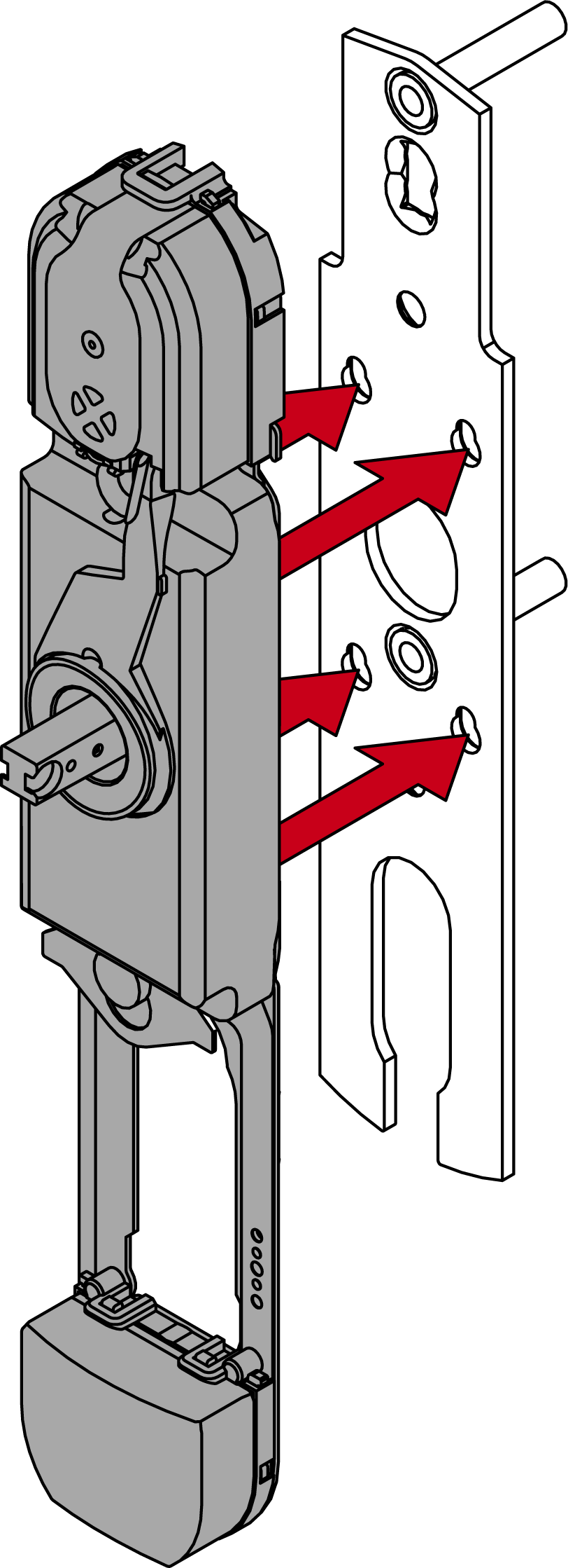
- Slide the module support upwards.
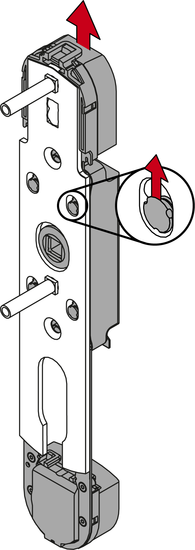
- Module support snaps into place.
- Fasten the module support to the fastening plate with the 12 mm screws (PH2, torque 3.0 Nm).

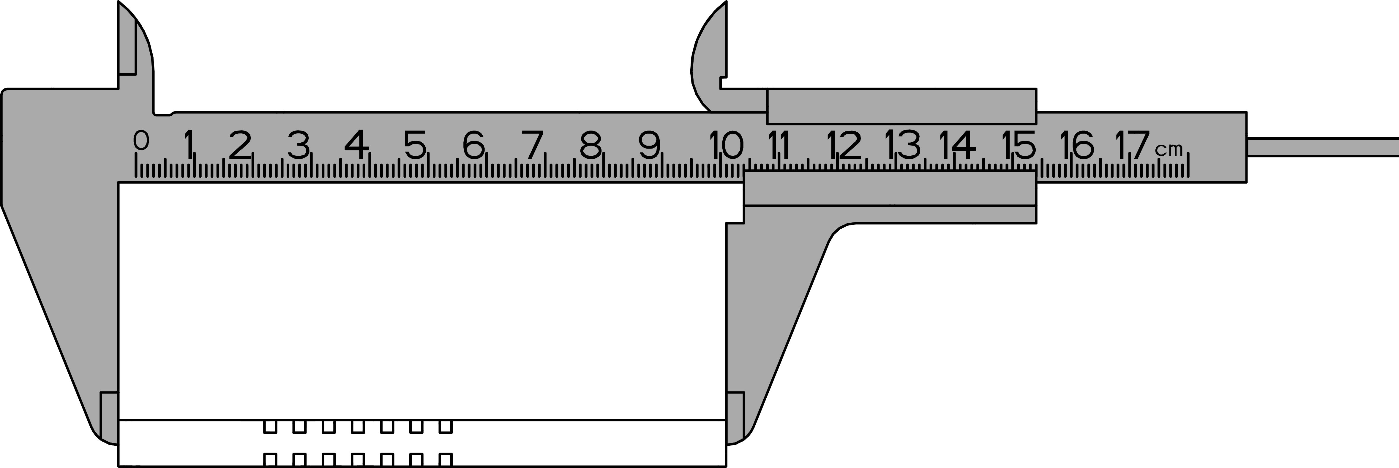
- Measure the total length of the spindle.
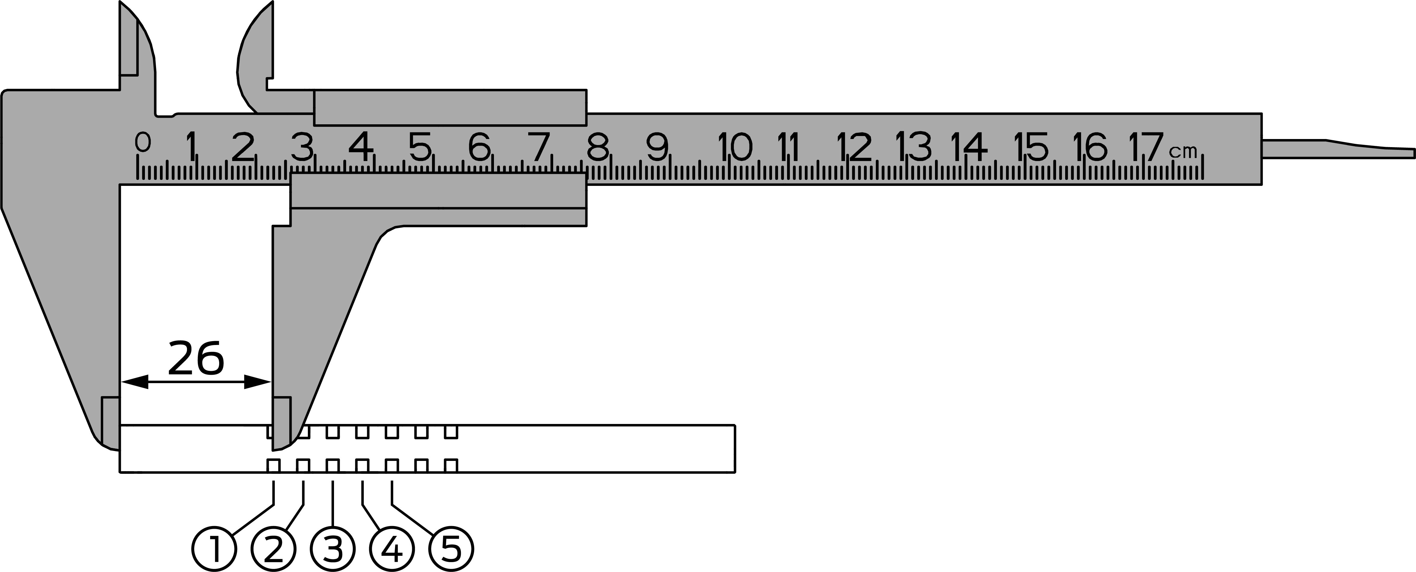
- Locate the inside of the spindle (four-edge end up to the centre of the first groove = 26 mm).
- Use the table to determine the position of the O-ring.
Area
Door thickness (mm)
Spindle length (mm)
Ring position
S
37 - <42
94
3
S
37 - <42
104
5
S
42 – <47
94
2
S
42 – <47
104
4
S
47 – <52
94
1
S
47 – <52
104
3
S
52 - <57
104
2
S
57 - 59
104
1
M
57 - <62
114
3
M
57 - <62
124
5
M
62 – <67
114
2
M
62 – <67
124
4
M
67 – <72
114
1
M
67 – <72
124
3
M
72 – <77
124
2
M
77 - 79
124
1
L
77 - <82
134
3
L
77 - <82
144
5
L
82 – <87
134
2
L
82 – <87
144
4
L
87 – <92
134
1
L
87 – <92
144
3
L
92 – <97
144
2
L
97 - 99
144
1
XL
97 - 182
O-ring is 30–35 mm from the cut end of the spindle.
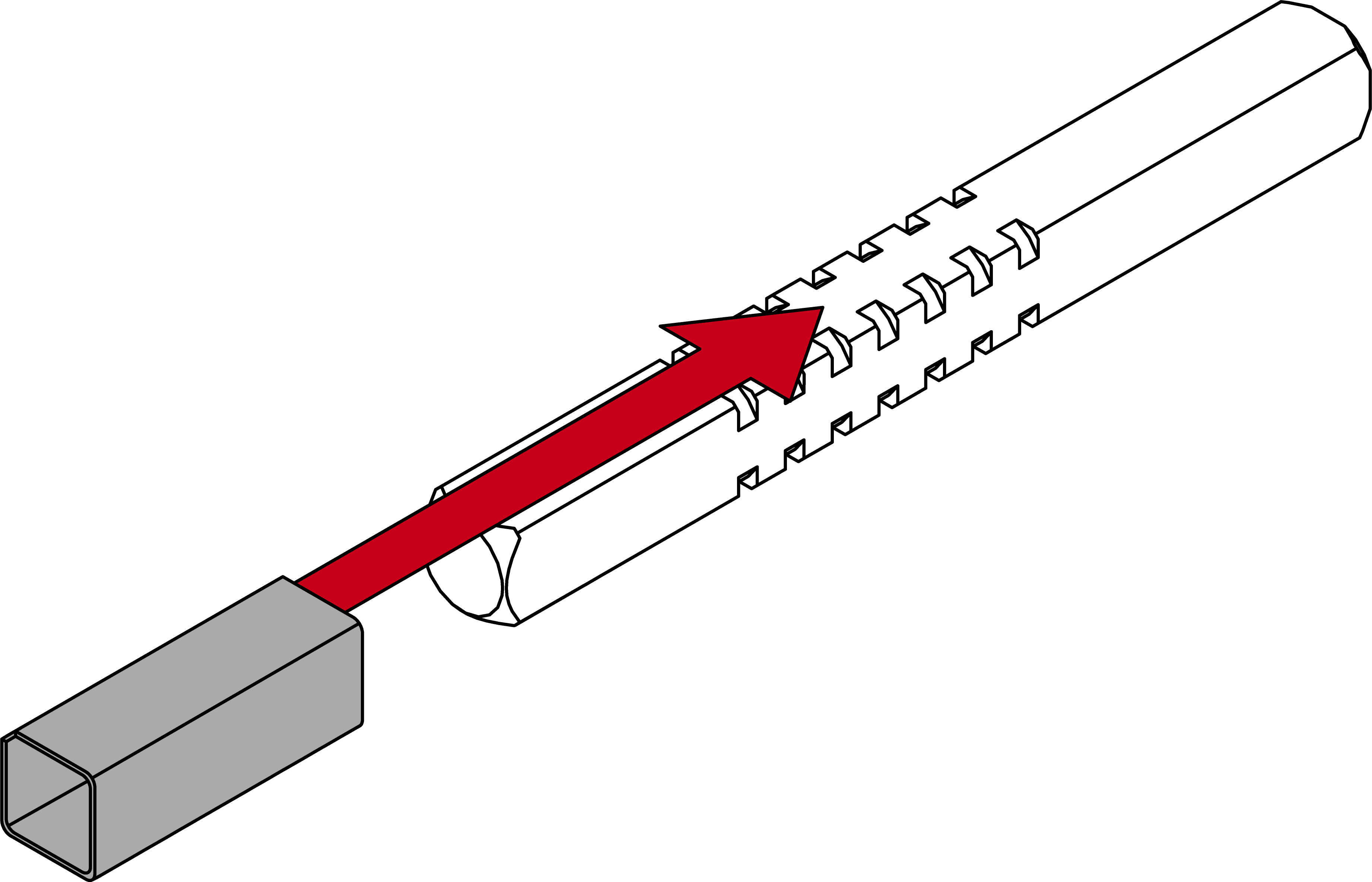
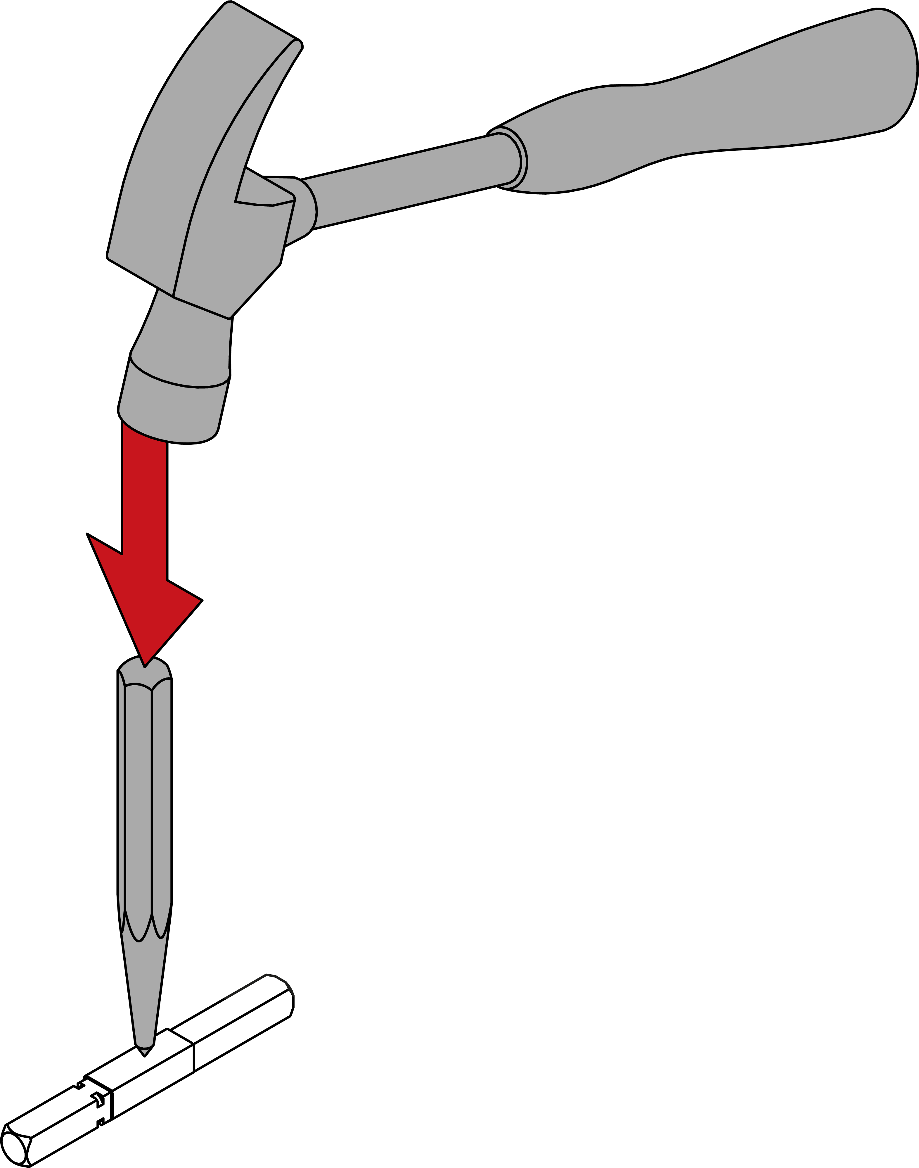
- For 8.5 mm and 10 mm spindle: slide the adapter sleeve into the centre of the spindle. Use a punch and hammer to make an indent in the adapter sleeve to prevent it from slipping.
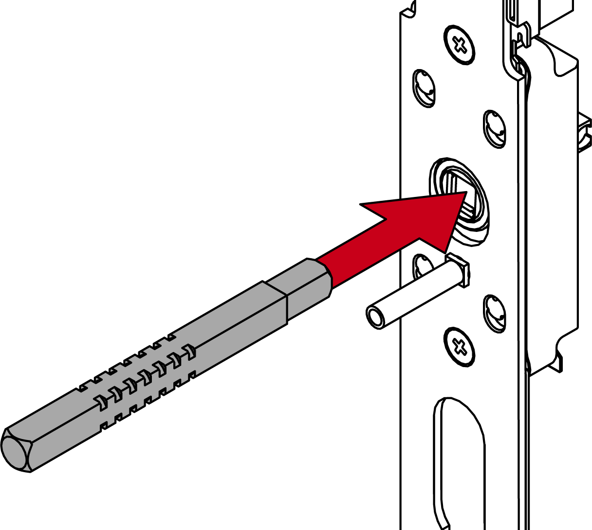
- Insert the outer side of the spindle into the fitting.
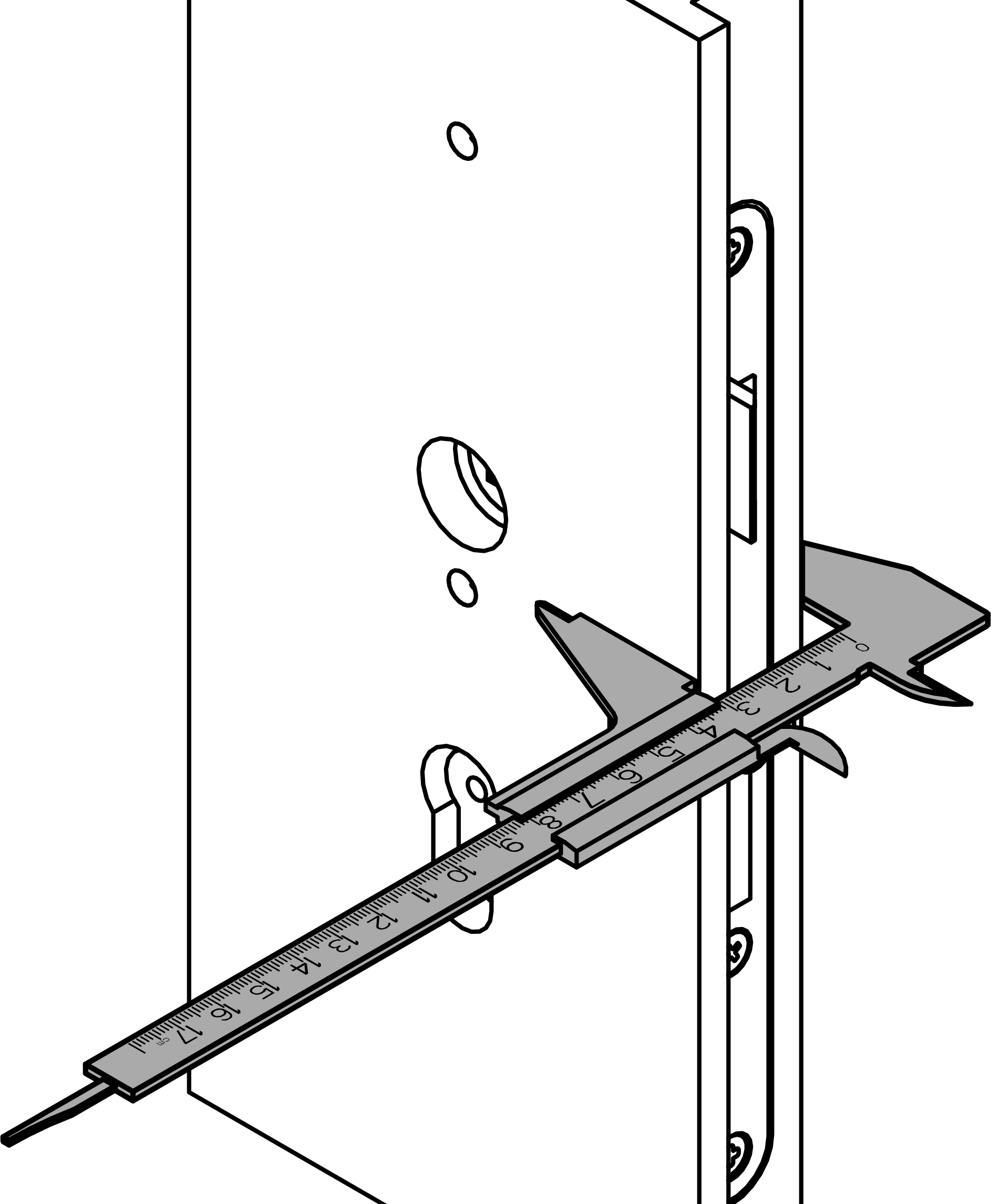
- Measure the door thickness.
Size
Door thickness (mm)
Screws
S
37 - <42
M5×30
S
42 - <50
M5×35
S
50 - 59
M5×45
M
57 - <69
M5×50
M
69 - 79
M5×60
L
77 - <89
M5×70
L
89 - 99
M5×80
X
97 - 182
M5 X
- Determine what screws are required for the door thickness measured.
- Insert the module support with the fastening plate into the outer side of the door.
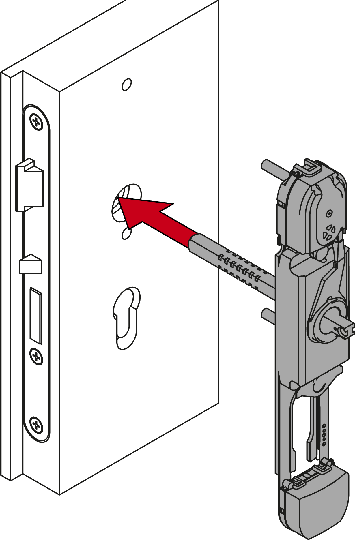
- When using a short backplate: insert the mounting disc into the larger fastening plate.
- When using X: insert the screws through the larger fastening plate and screw them together with the threaded sleeve and threaded rod.
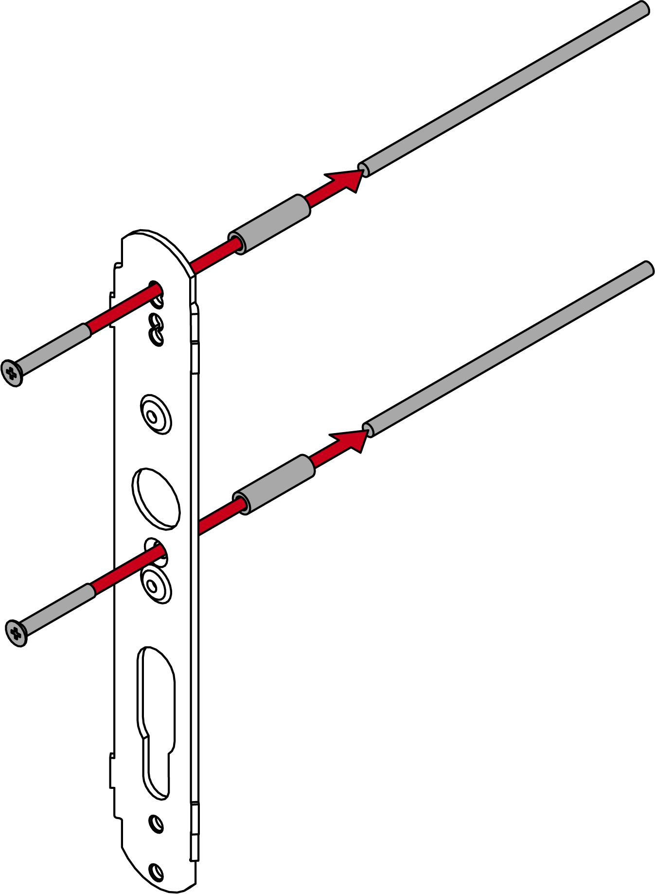
- Place the inner fastening plate and the mounting disc on the spindle.
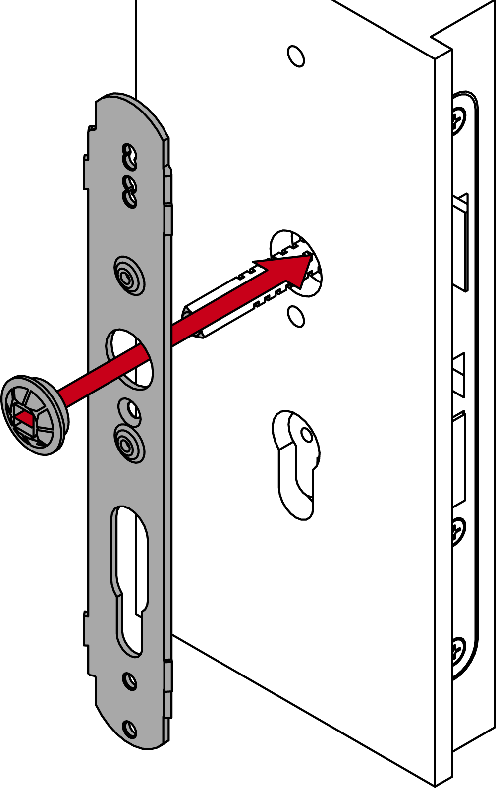
- Use the screws provided to fix the larger fastening plate onto the module support with the smaller fastening plate (PH2; long backplate: middle/top; short backplate: middle/bottom; torque: 1.1 Nm).
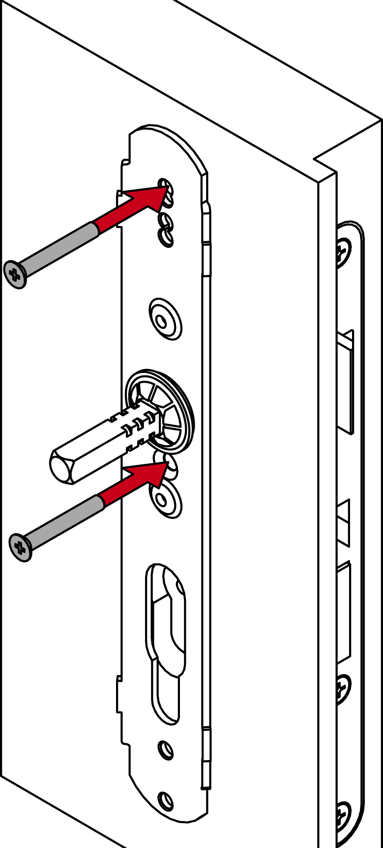
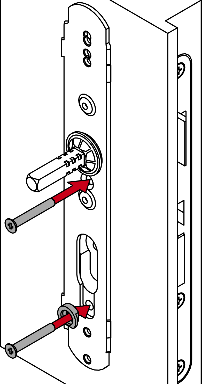

- Remove the mounting disc from the spindle again.

- Slide the O-ring onto the calculated groove.

- For 7 mm spindle: Place the adapter sleeve in the inside handle in such a way that the recess faces the grub screw.
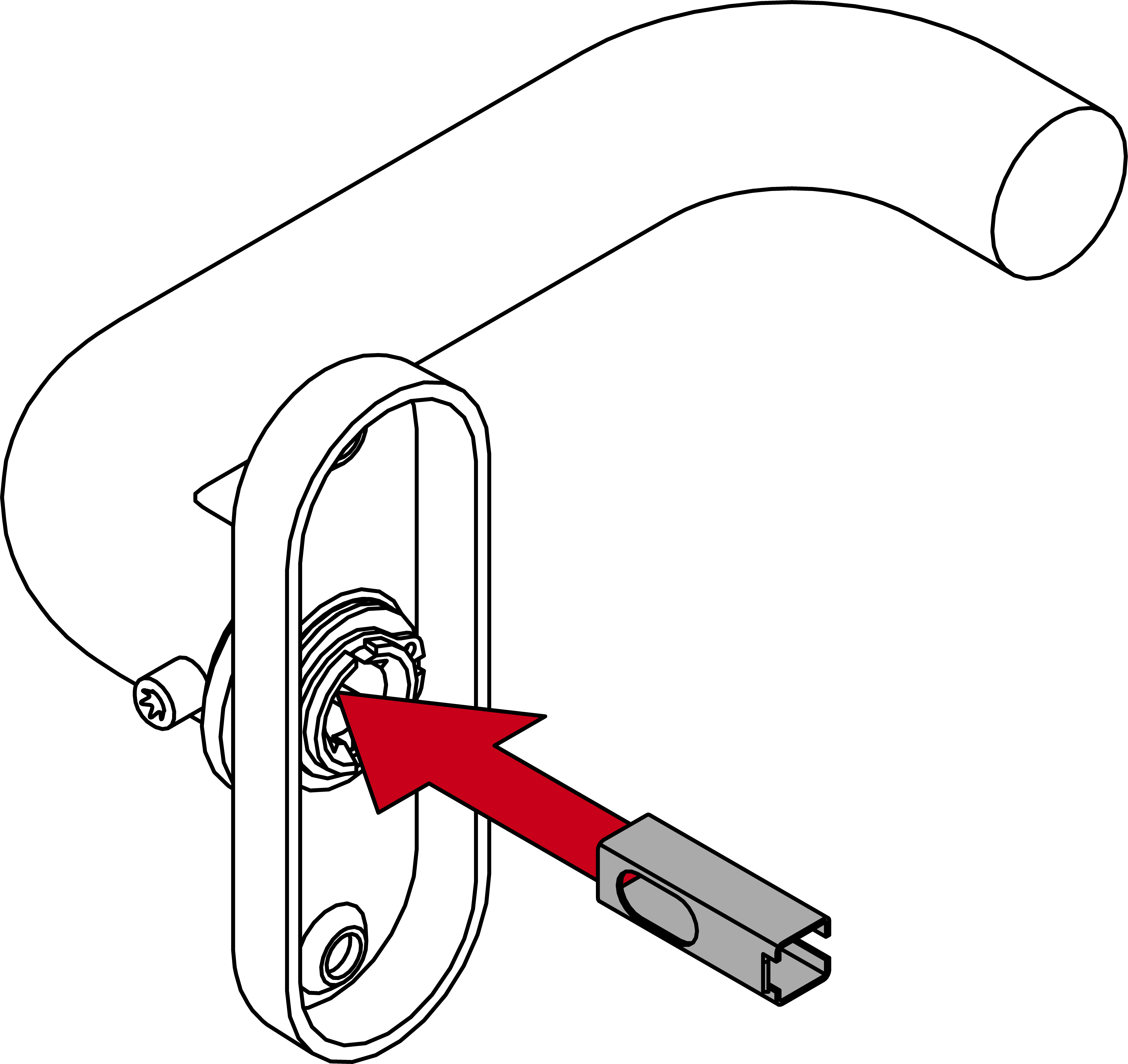
- Determine the required direction of rotation for your inside handle.
- Insert the spring element appropriately.
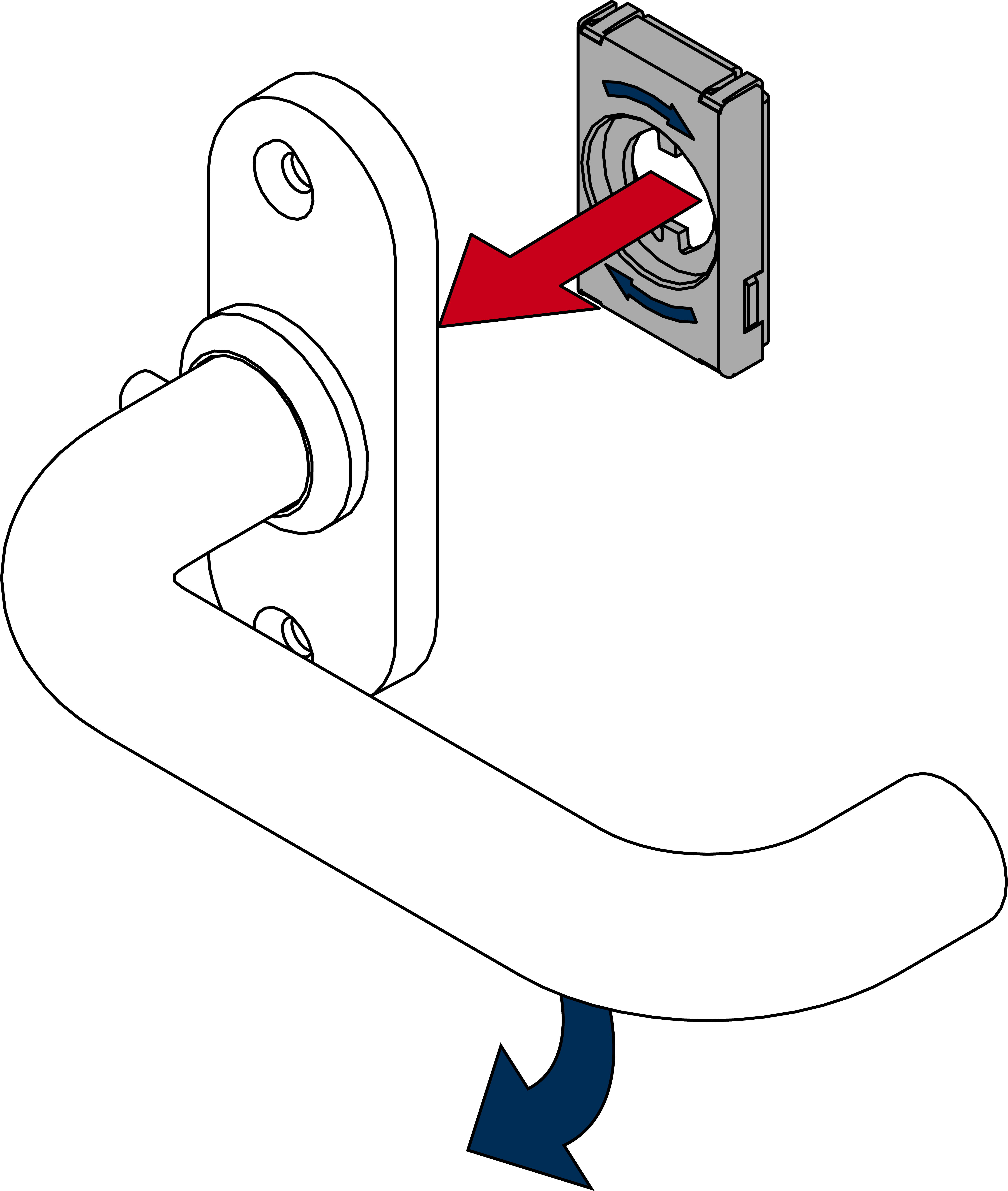
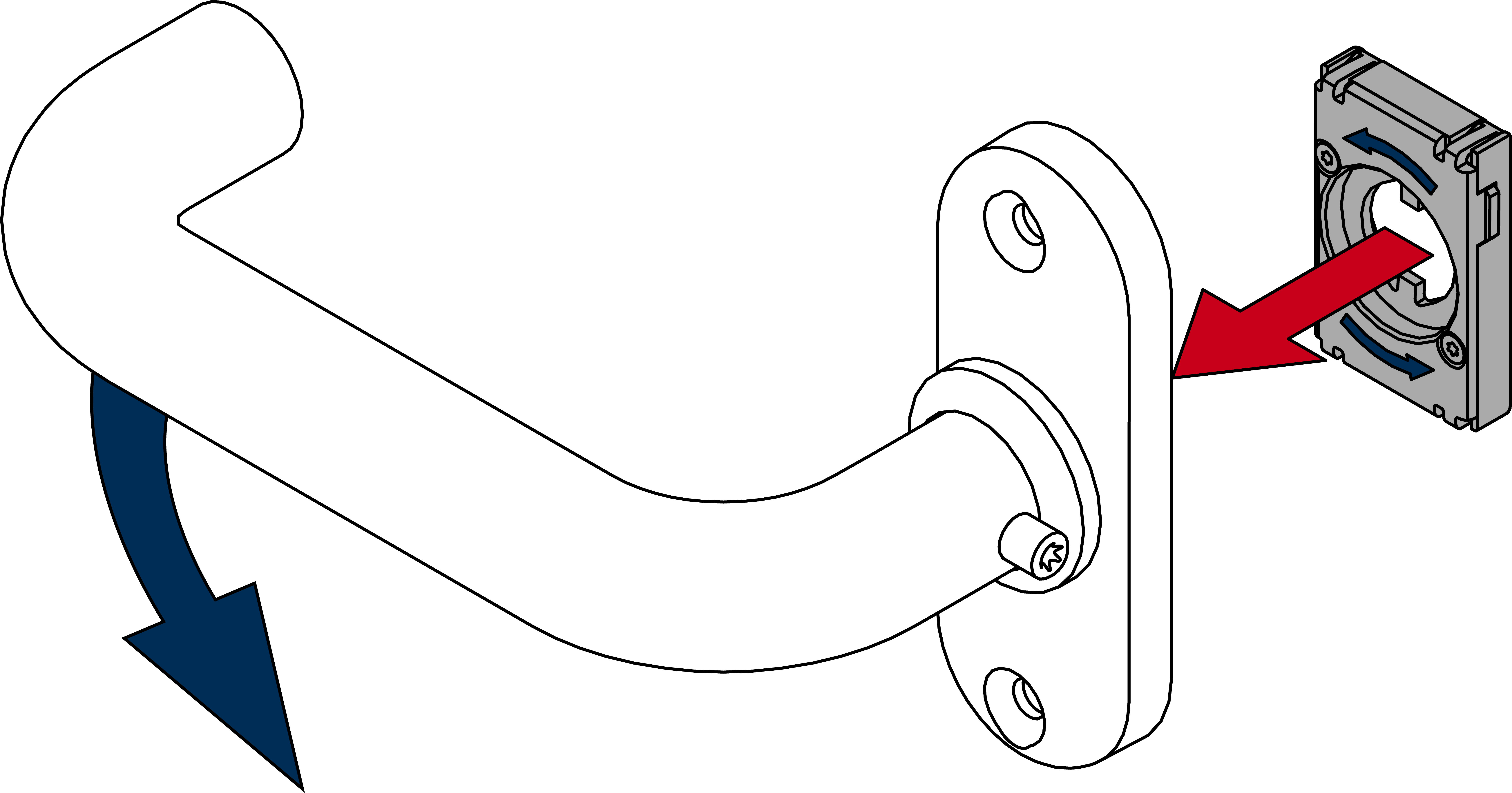
- When using rectangular or offset inside handles (*B, *D, *E, *F): slide the cover onto the inside handle before screwing it into place.
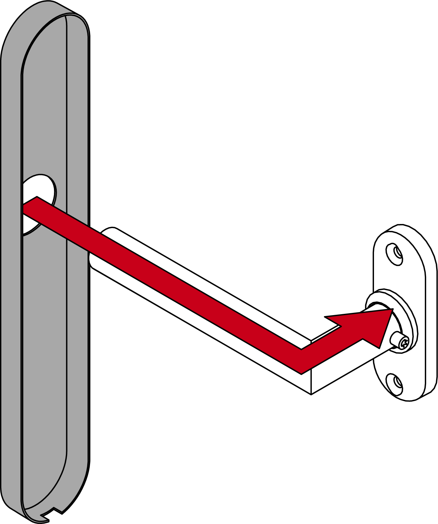
- Use the 12 mm screws to fix the module support onto the fastening plate (PH2; torque: 3.0 Nm).
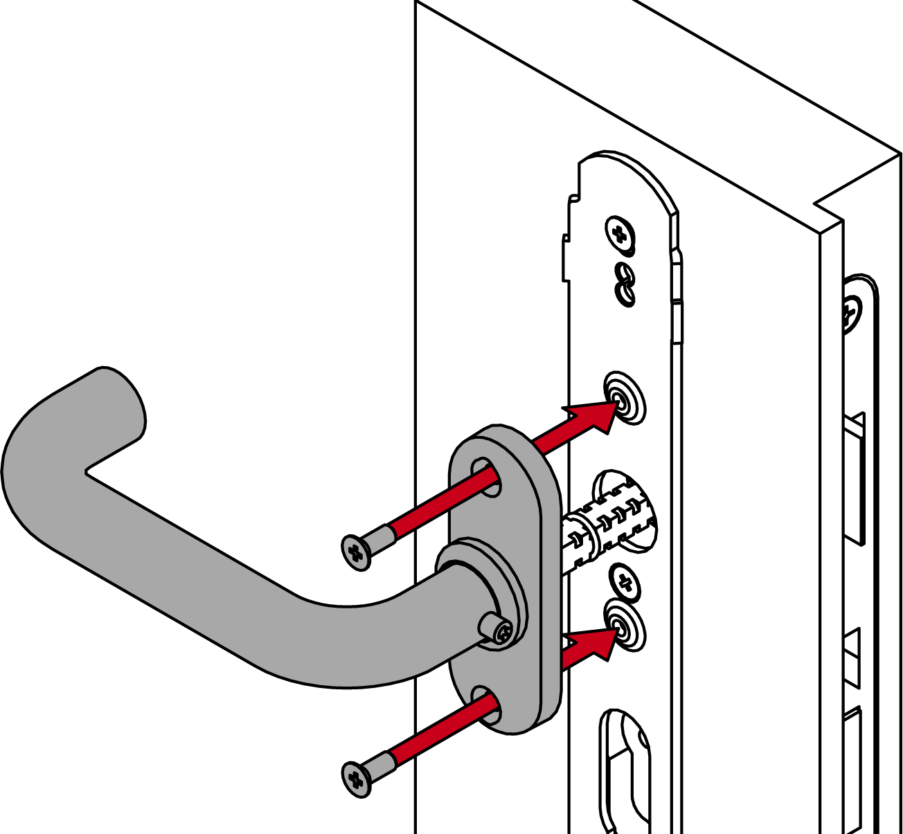
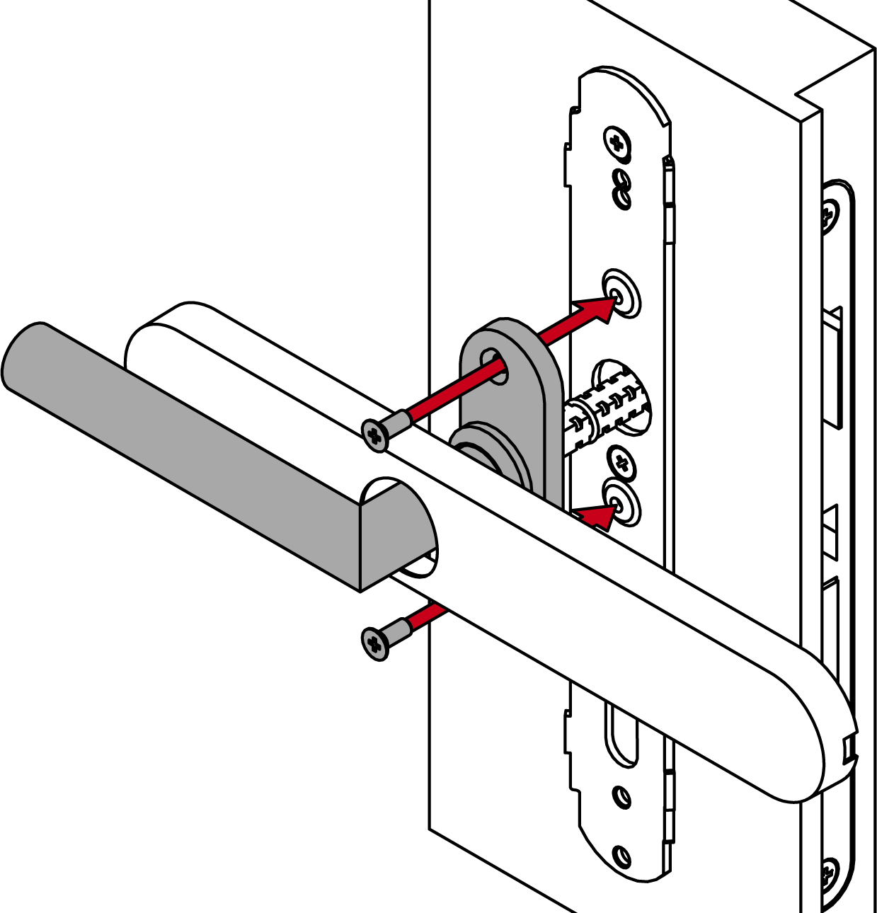
- Fasten the handle firmly with the grub screw (TX15; torque: 5.0 Nm).

- When using rectangular or offset inside handles (*B, *D, *E, *F): straighten the cover by turning it back into place.
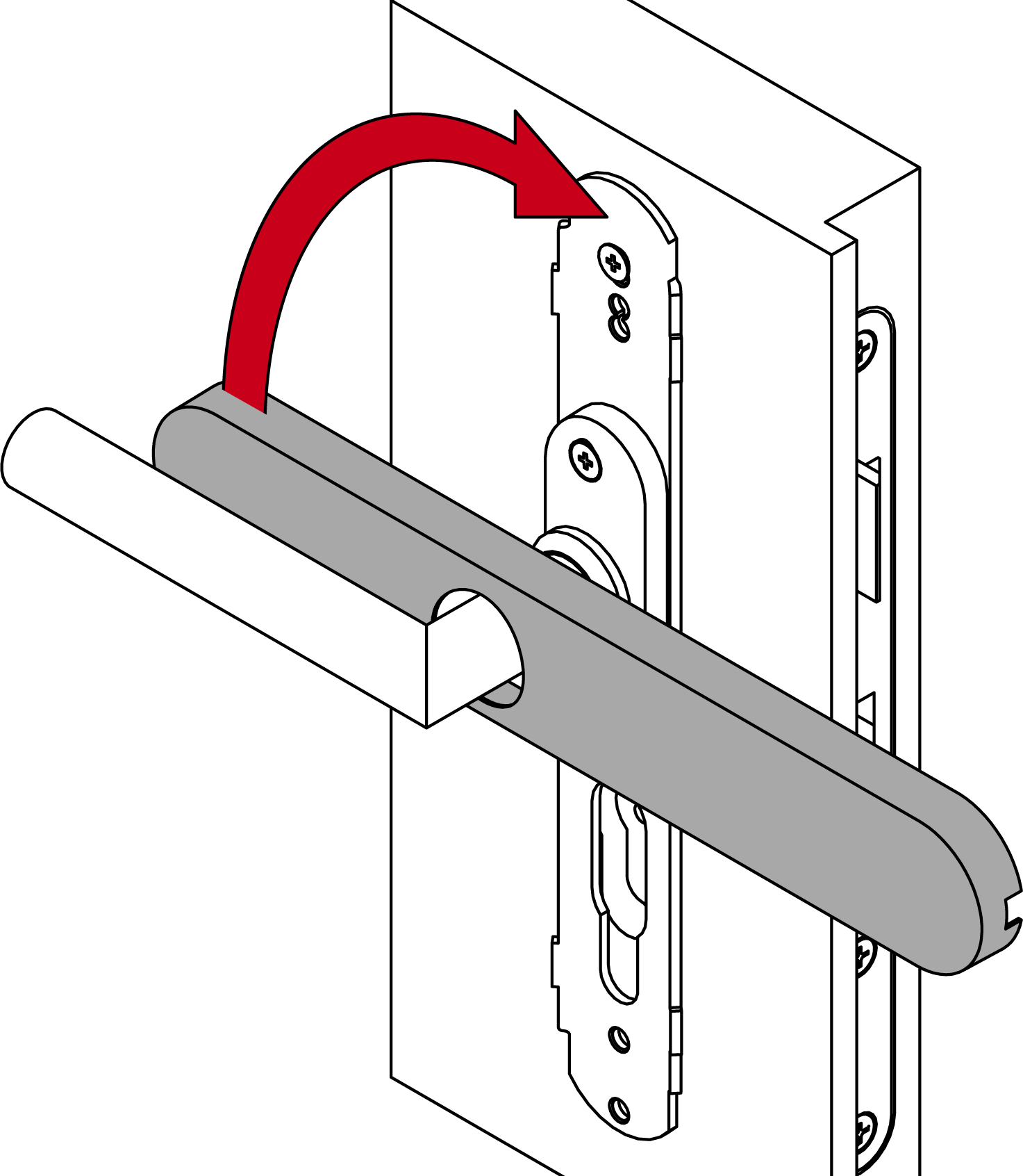
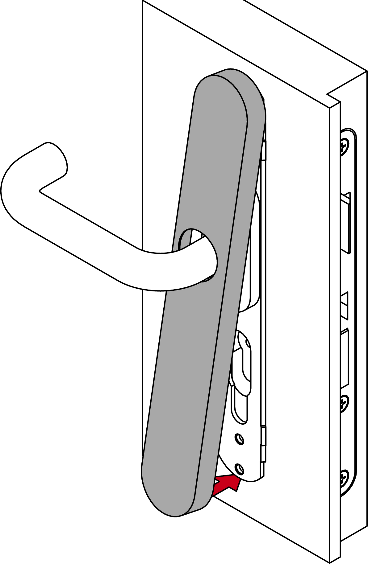
- Attach the cover at the top and press it firmly until it clicks into place.
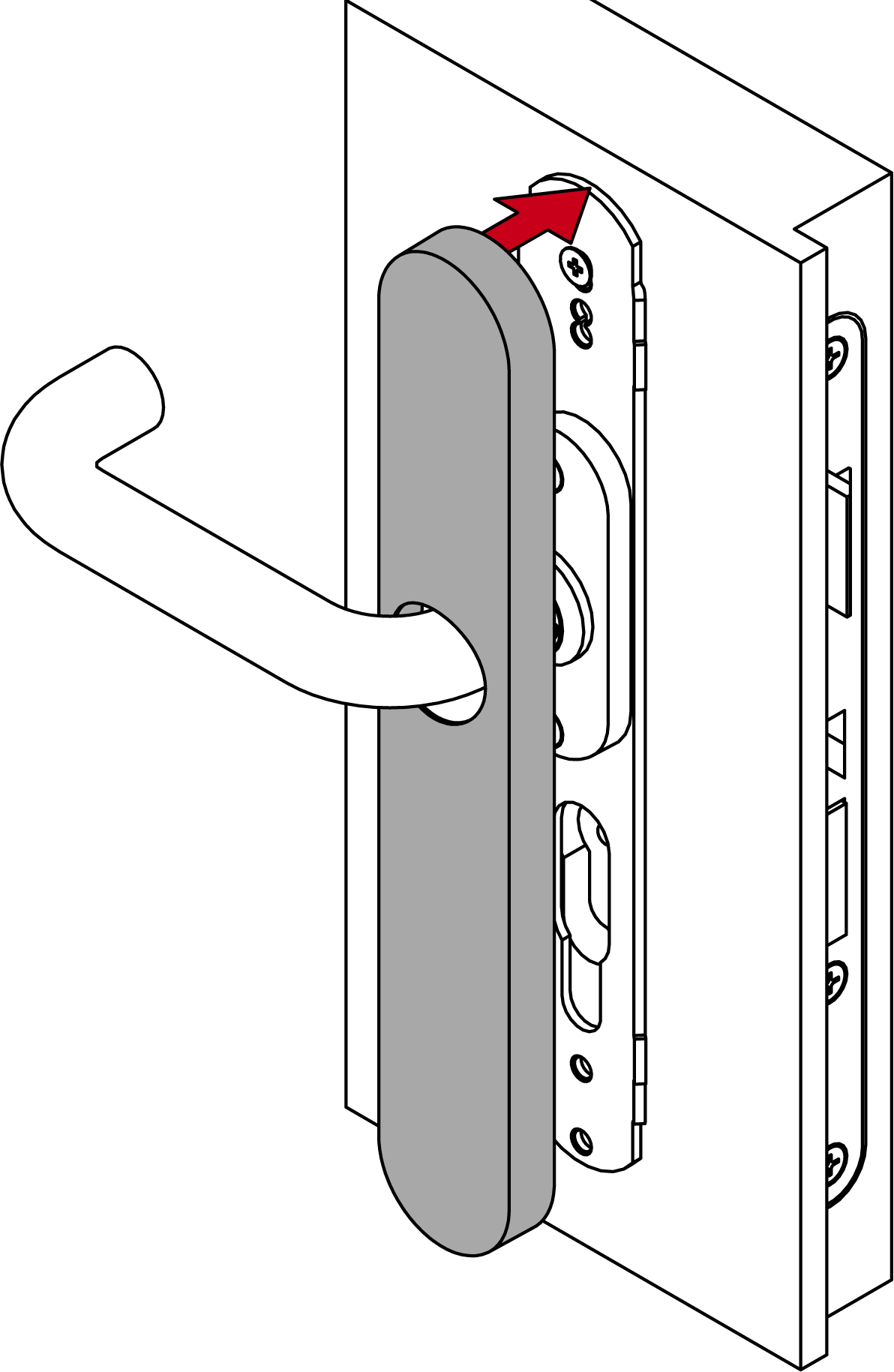
- Press the bottom of the cover to close it.
- Place the cover on top of the fastening plate.
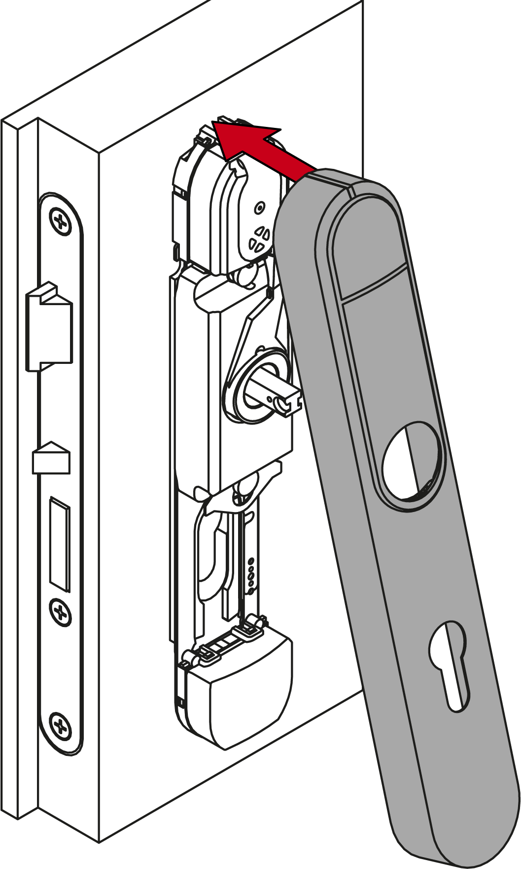
- Fold down the cover.
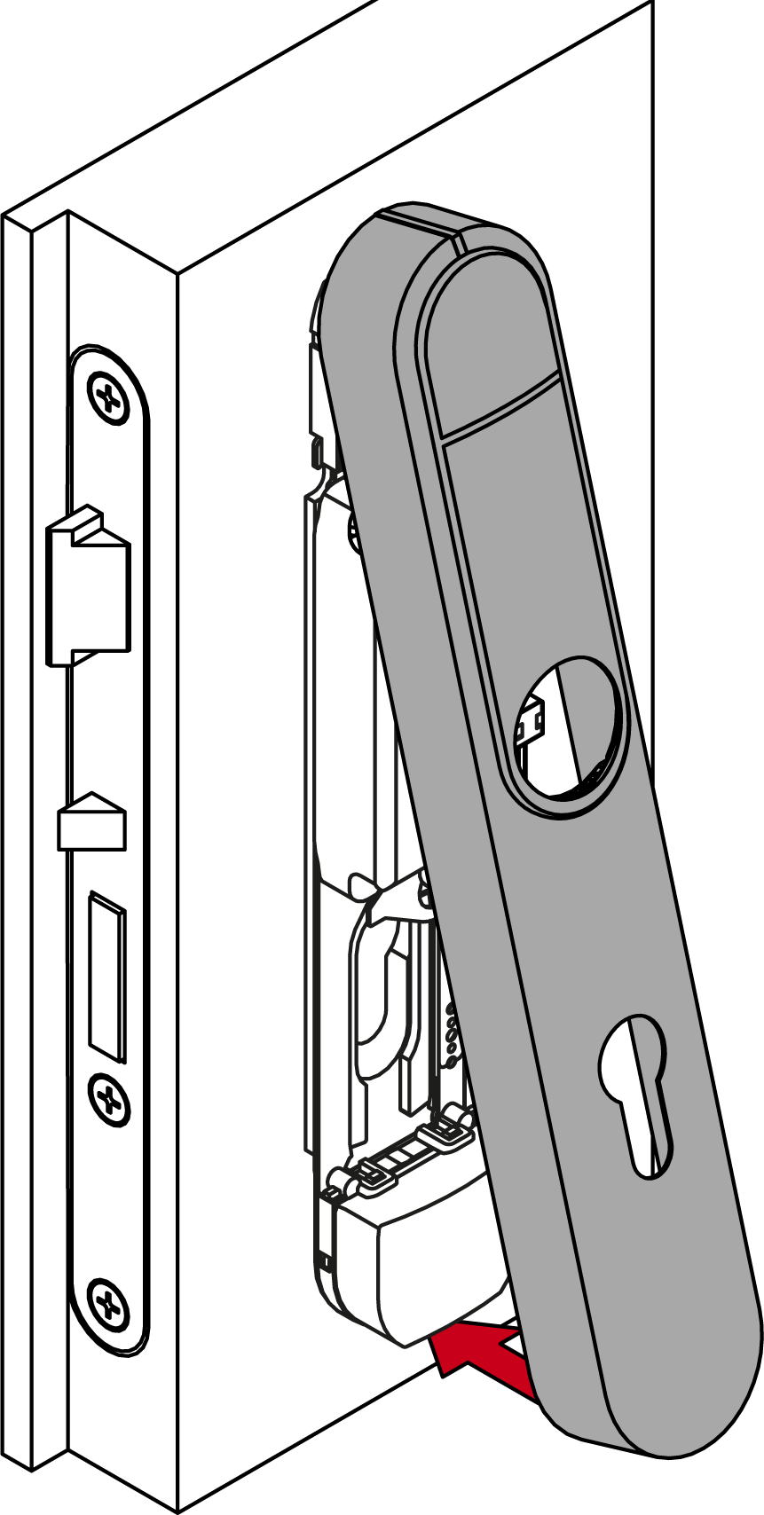
- Slide the cover upwards.
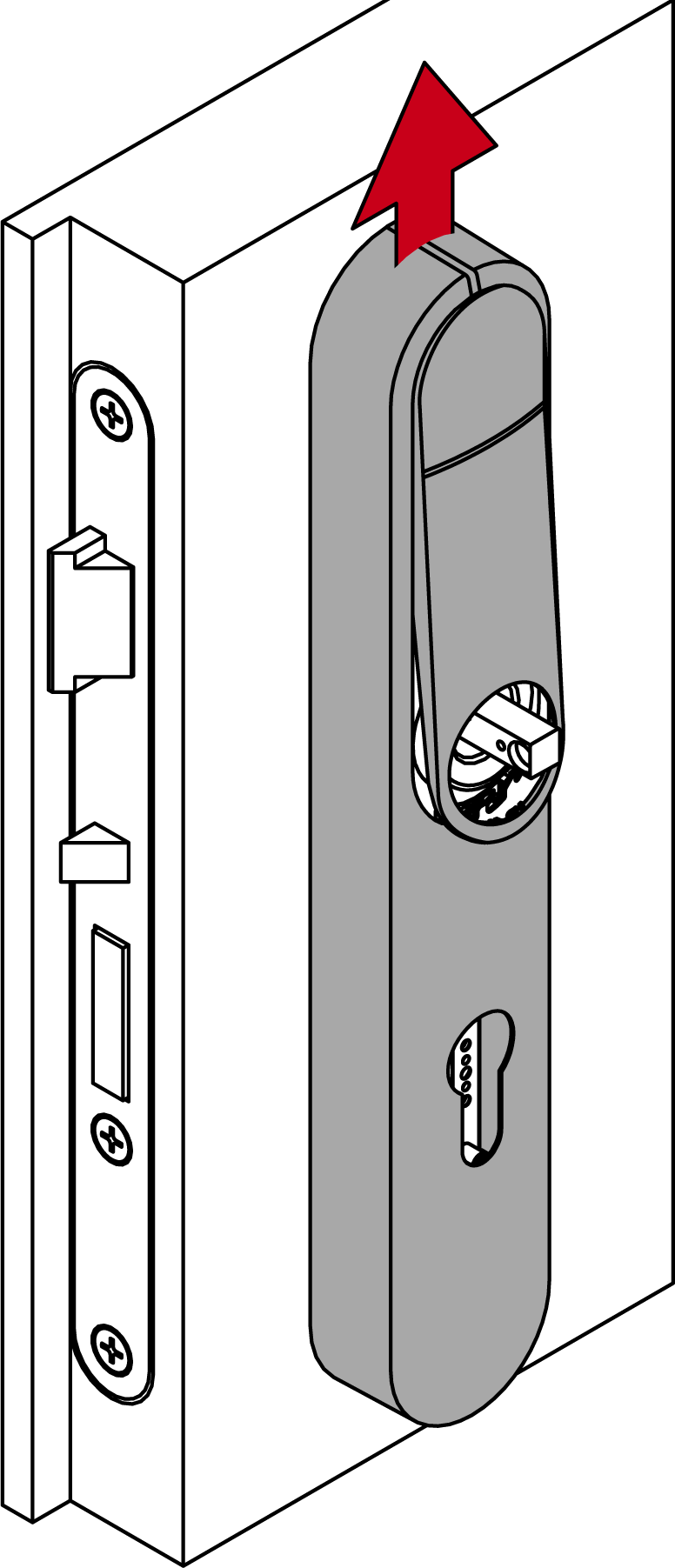
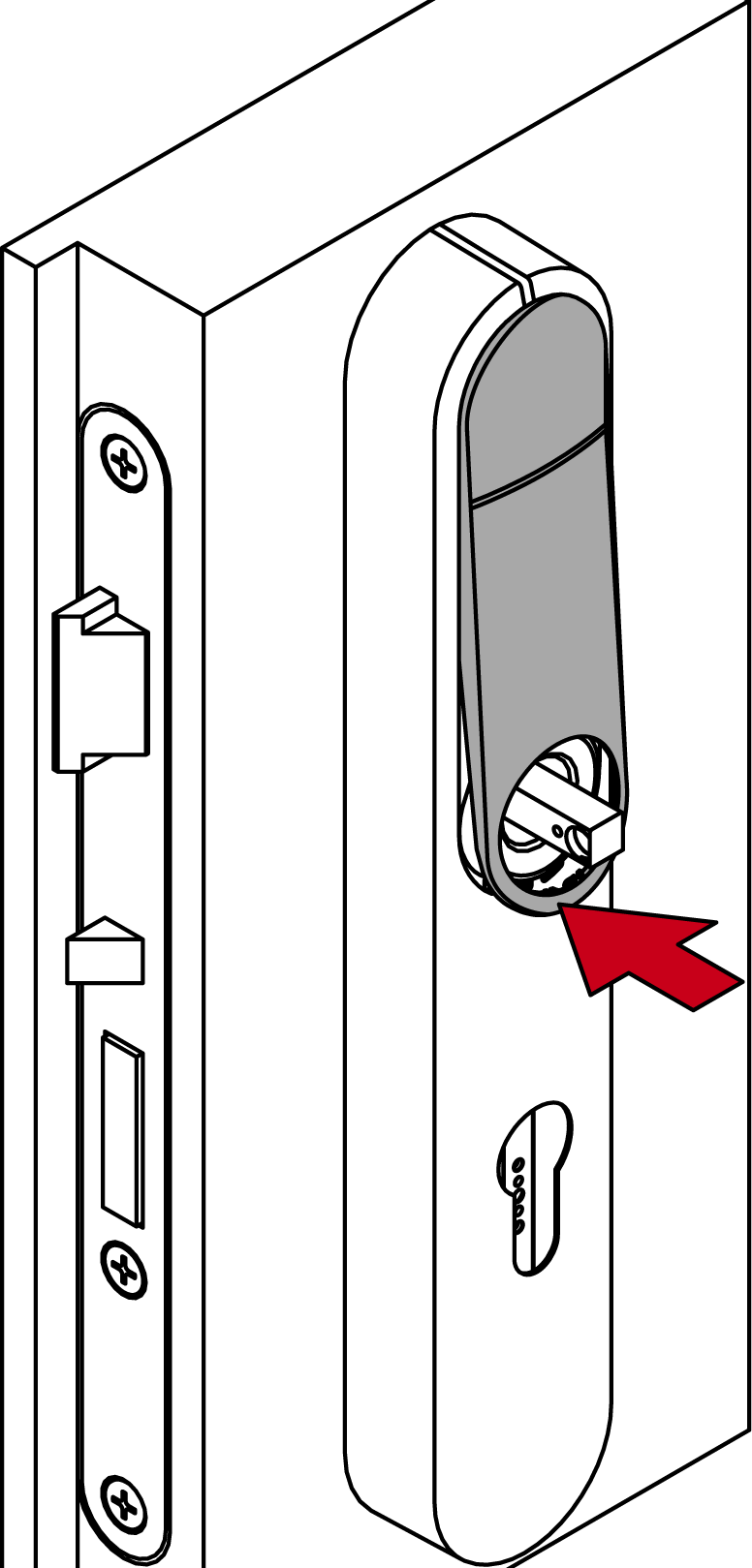
- Press the inlay into place.
- Fit the outside handle.
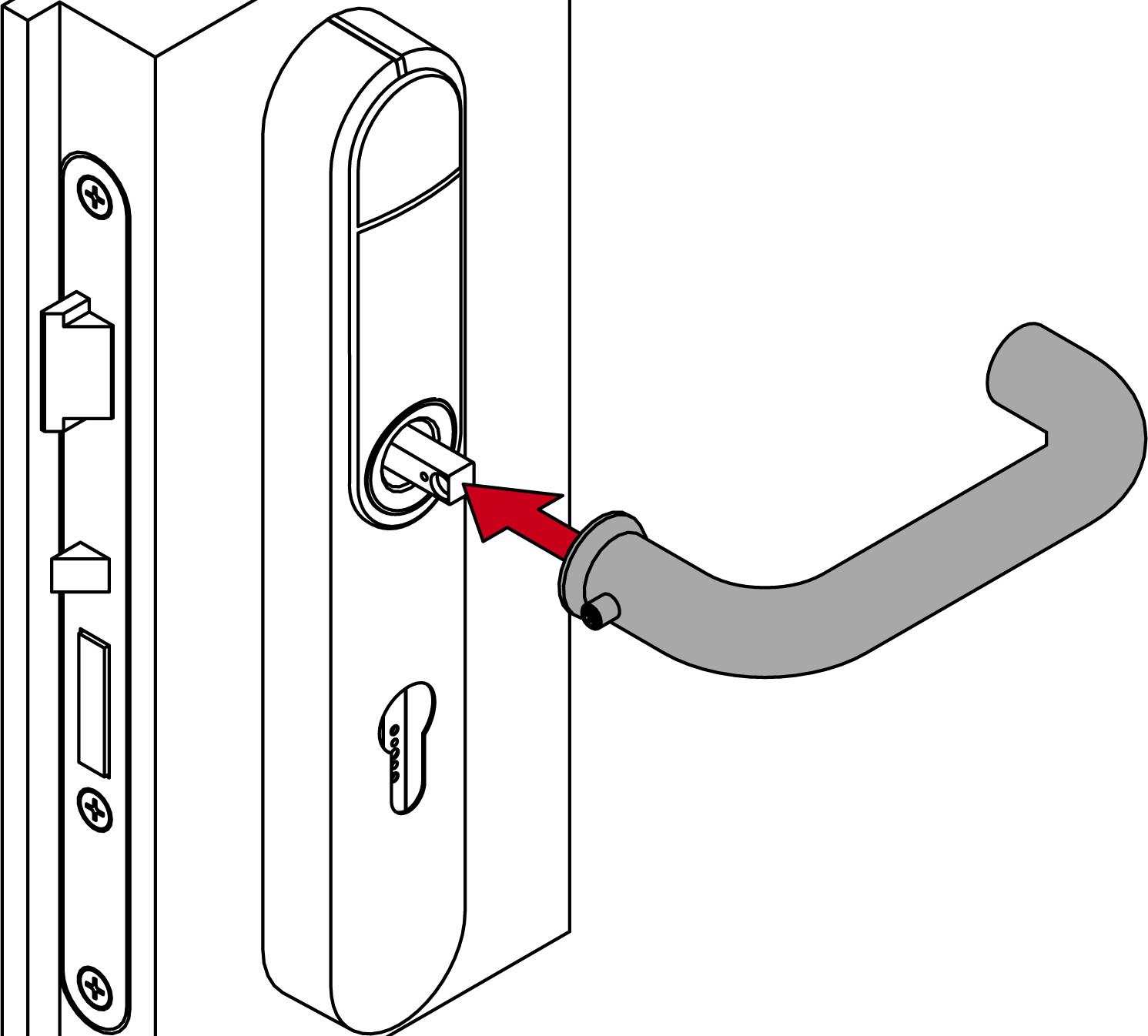
- Use the grub screw to fasten the outer handle (TX15, torque 5.0 Nm) into position.

- SmartHandle AX Advanced fully installed.