Structure - System description WO
Locking cylinders basically consist of two halves:
Master (Central Unit = CU) | Slave |
|---|---|
Thumb-turn cannot be removed. | Knob can be removed for installation. |
Identifier: Black ring between thumb-turn and profile cylinder. |
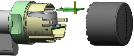
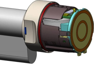
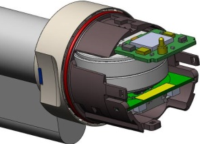
Locking cylinders consist of several parts:
| Control Unit (CU): Assembly under the battery compartment of the master knob |
| Card reader (Card Reader = CR): Master reader (for cylinders which can be read on both sides (FD and BL): additional slave reader) |
| LockNode (LN): Assembly above the battery compartment of the master knob |
| Batteries in the battery compartment of the master knob |
The locking cylinder should always be installed with the inner side inside. You will find the marking on the inside:
- In the dimensional drawings (see Dimensional drawings cylinder)
- On the profile housing (IN)
Comfort (CO) | Page | Behaviour (disengaged state) | Components | Batteries |
|---|---|---|---|---|
Master | Outside | Freely rotating |
| 2 |
Slave | Inside | Permanently engaged | No electronics | None |
Freely rotating (FD) | Page | Behaviour (disengaged state) | Components | Batteries |
|---|---|---|---|---|
Master | Inside | Freely rotating |
| 2 |
Slave | Outside | Freely rotating | Second control unit | 2 |
Anti-panic freely rotating (AP2 FD) | Page | Behaviour (disengaged state) | Components | Batteries |
|---|---|---|---|---|
Master | Outside | Freely rotating |
| 2 |
Slave | Inside | Engage not possible | No electronics | None |
Anti-panic, read on both sides (AP2 BL) | Page | Behaviour (disengaged state) | Components | Batteries |
|---|---|---|---|---|
Master (inner) | Reversible | Freely rotating |
| 2 |
Slave (external) | Freely rotating |
| 2 |
NOTE

Programming error during interrupted or changed master-slave pairing
The master and slave are factory configured as belonging together. Replacing knobs will result in programming errors.
Master and slave communicate during programming.
- Make sure that the master and slave are physically connected during programming.