Installing the fitting - SmartHandle AX Advanced SmartIntego
- Door pre-drilled.
- PH2 screwdriver at hand.
- TX15 screwdriver at hand.
- Have an SW6 hex slotted-head screwdriver ready.
- Have an SW5 hex slotted-head screwdriver ready.
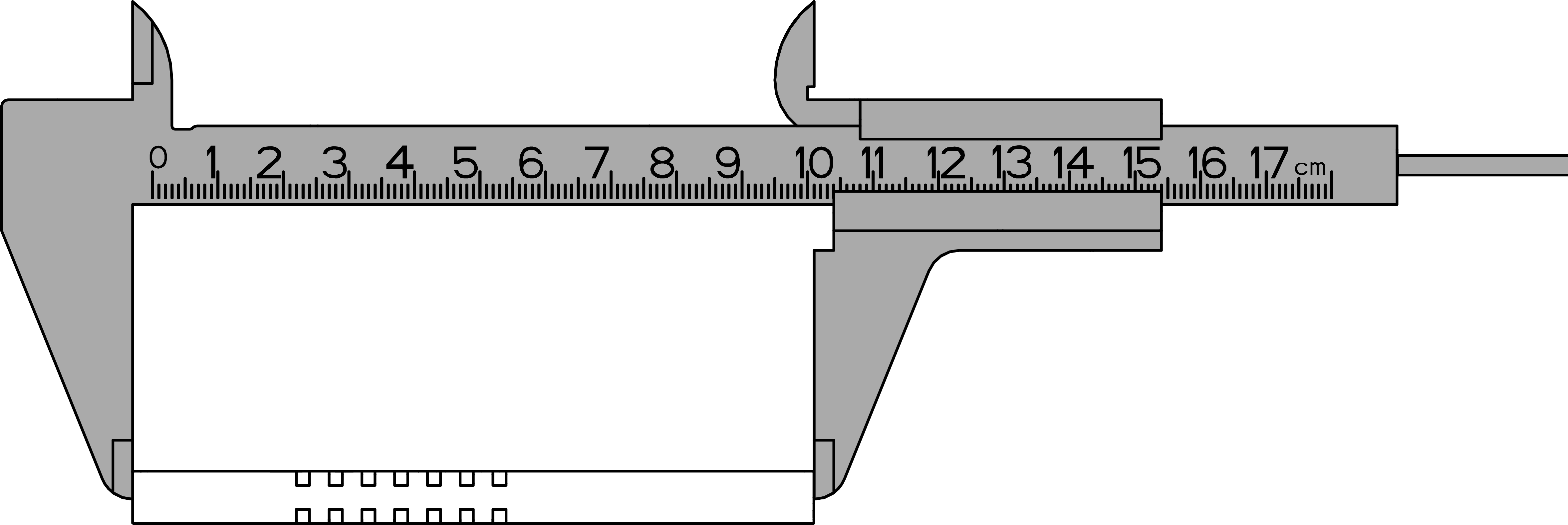
- Caliper gauge at hand.
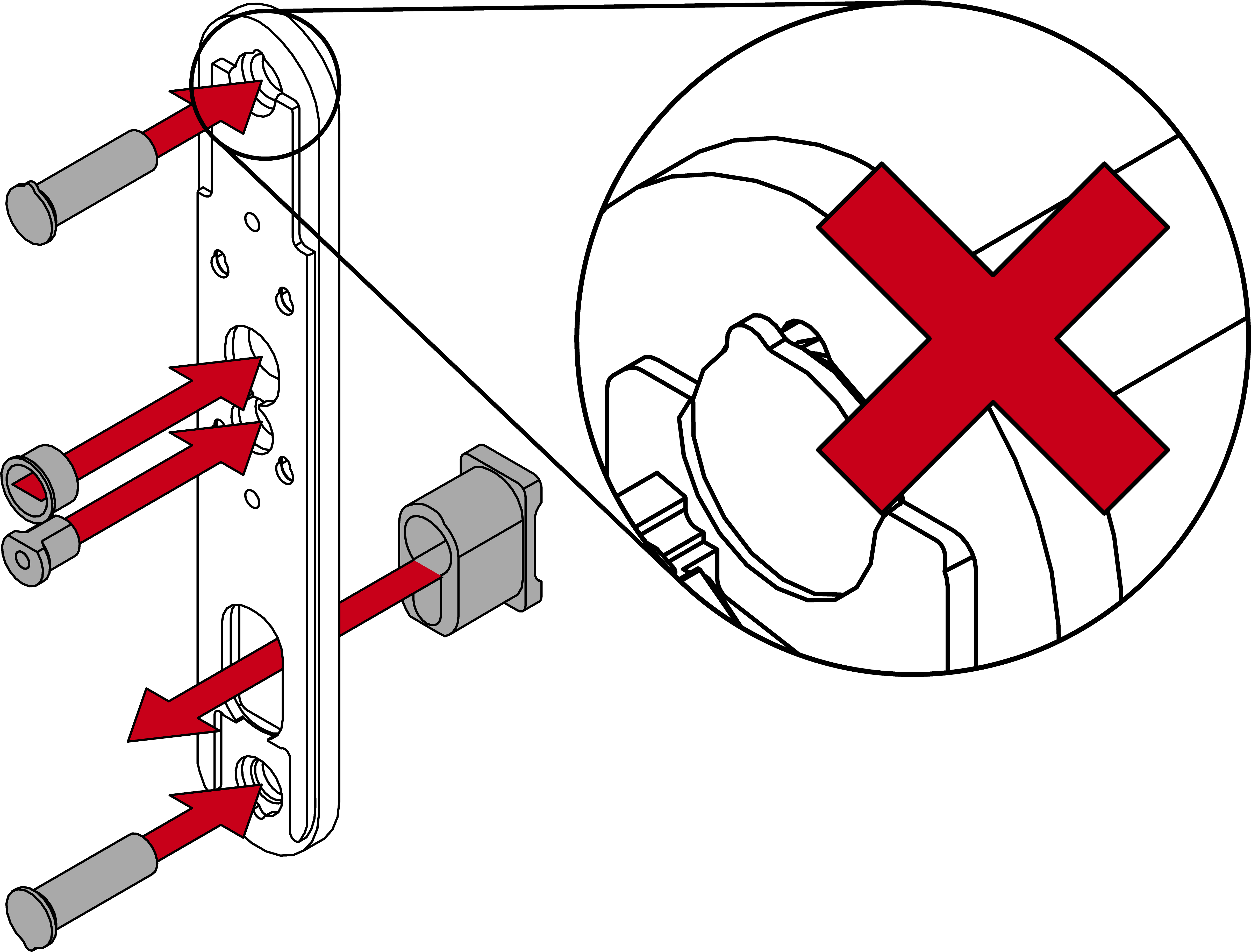
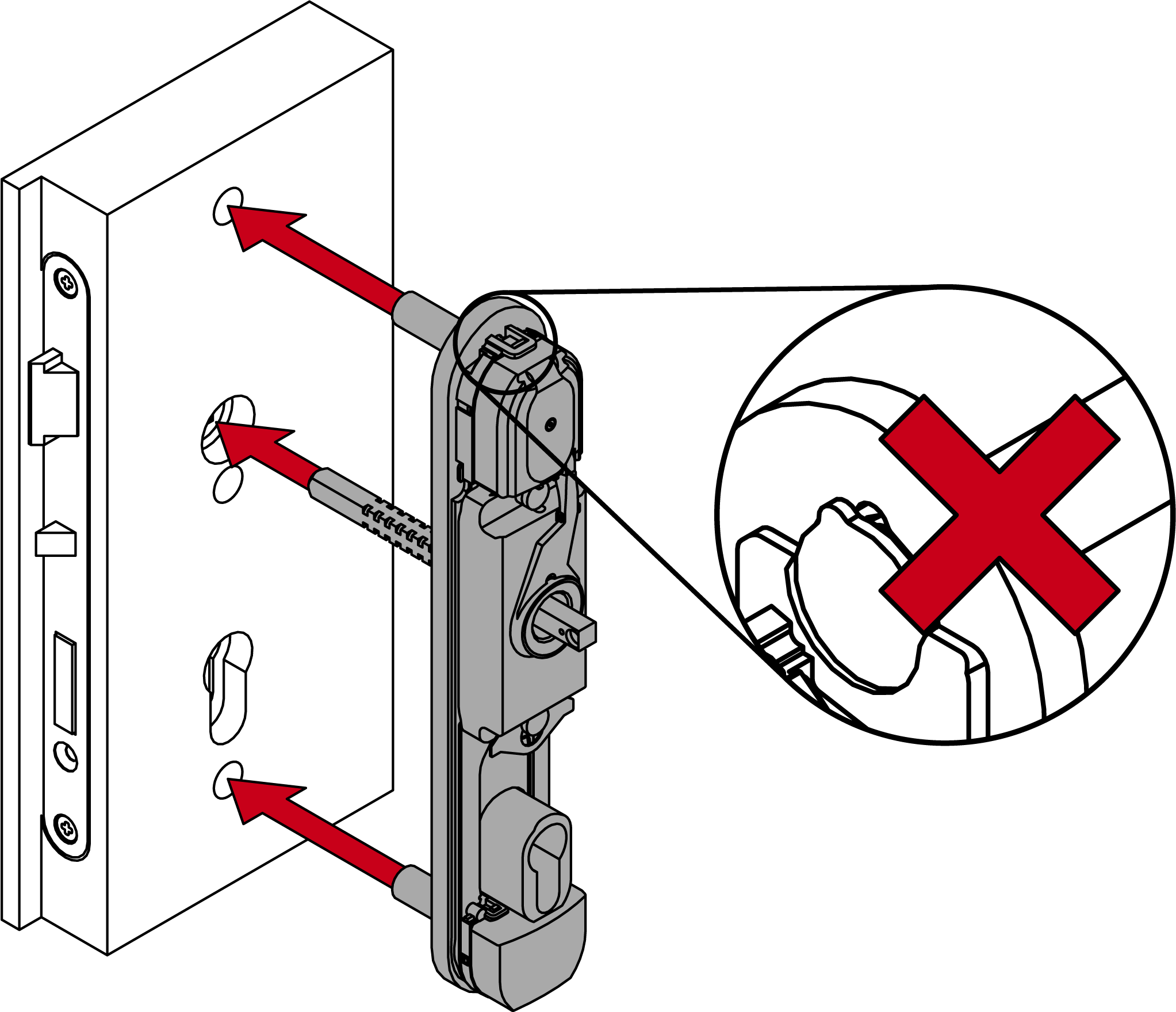
- Insert the spindle protective tube, the locking cylinder protection and the sleeve nuts into the fixing plate (short sleeve nut in the middle).
- For 7 mm spindle: Insert the adapter shoe into the spindle mount on the module support.
- Insert the module support into the fastening plate.
IMPORTANT
Damage to the sleeve nuts due to improper insertion
If the sleeve nut tabs are not located in the recesses, they can be damaged during further installation. In such cases, the sleeve nut can rotate unintentionally, which makes installation/removal difficult.
- Ensure that the sleeve nut tabs are located in the recesses.
- Slide the module support upwards.
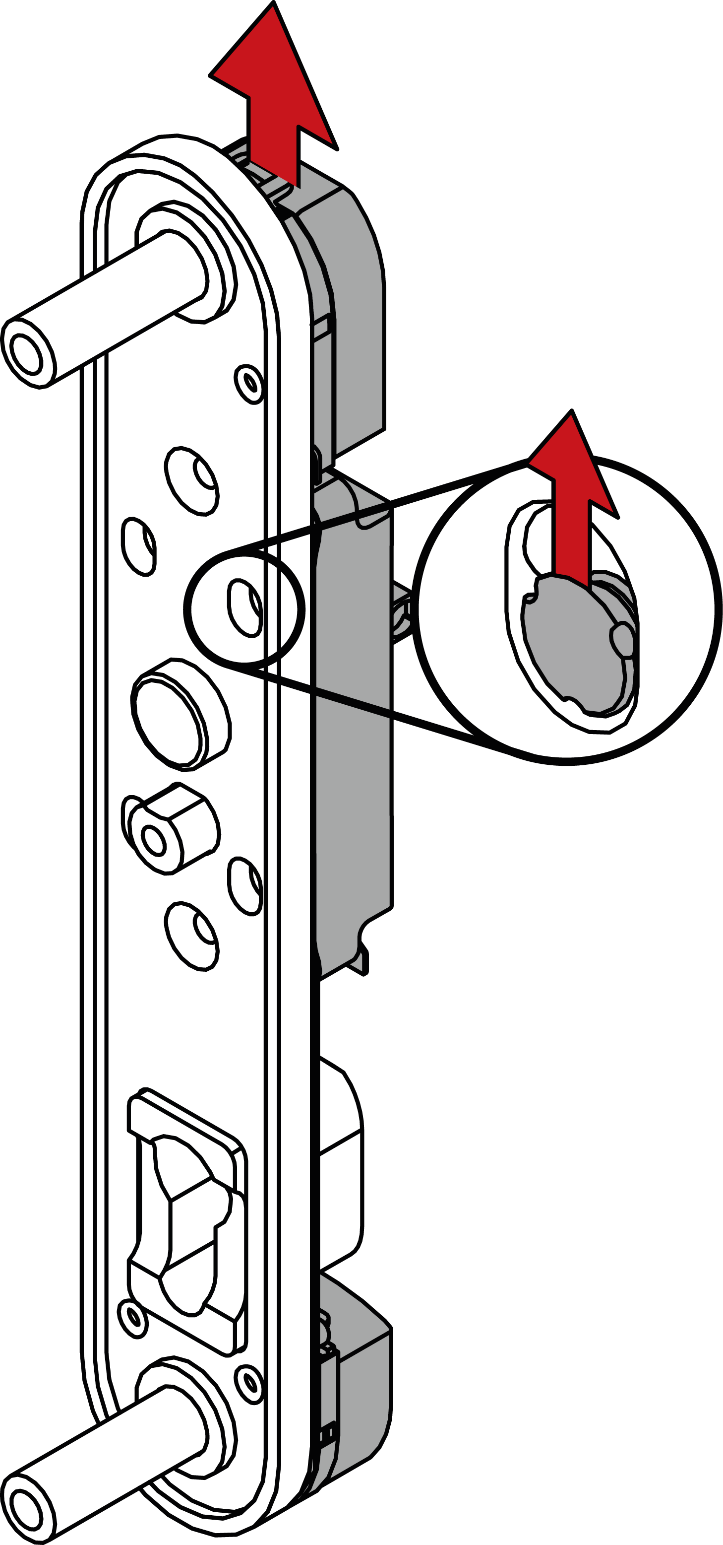
- Module support snaps into place.
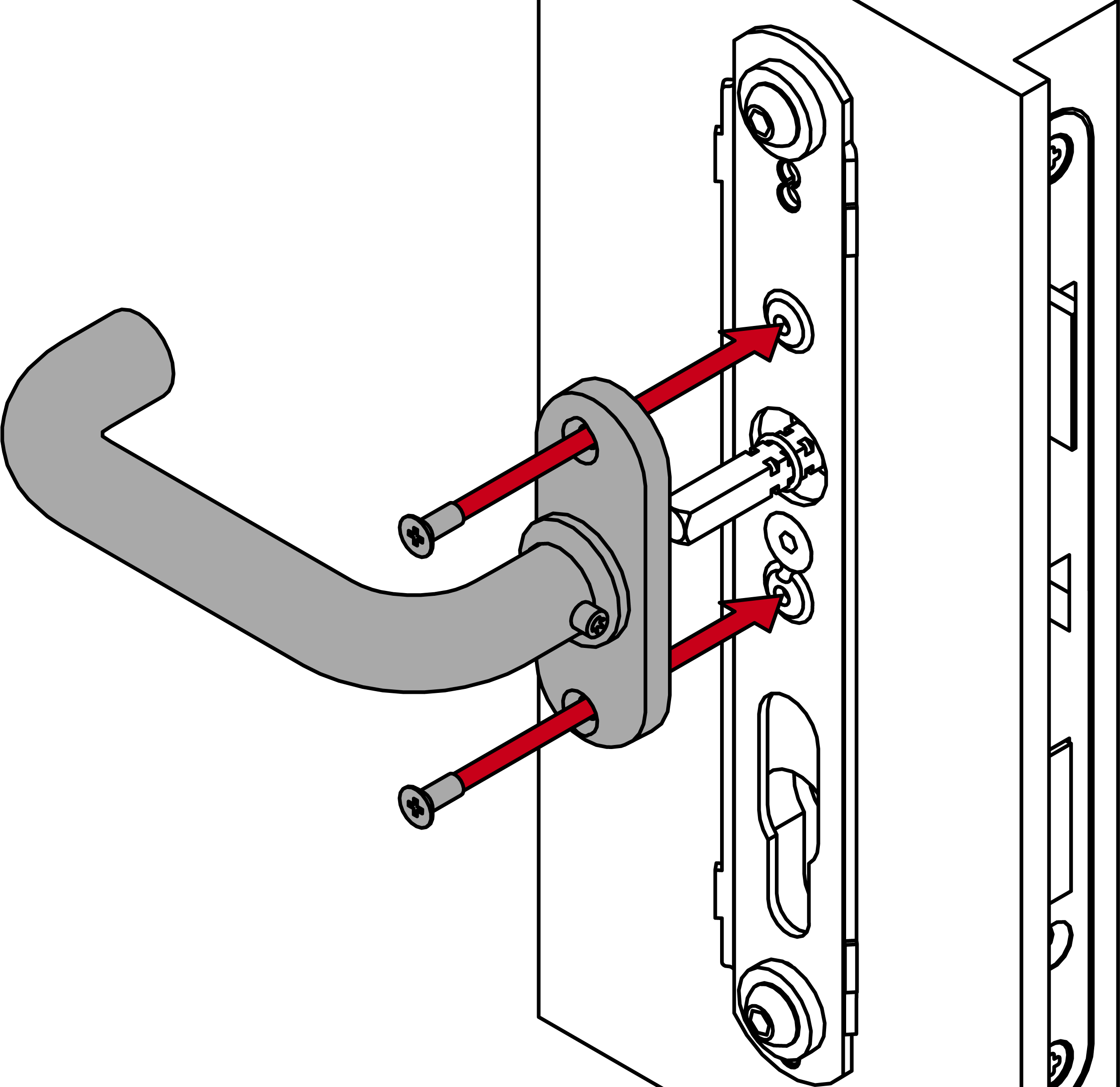
- Fasten the module support to the fixing plate with the 16 mm screws (PH2, torque 3.0 Nm).

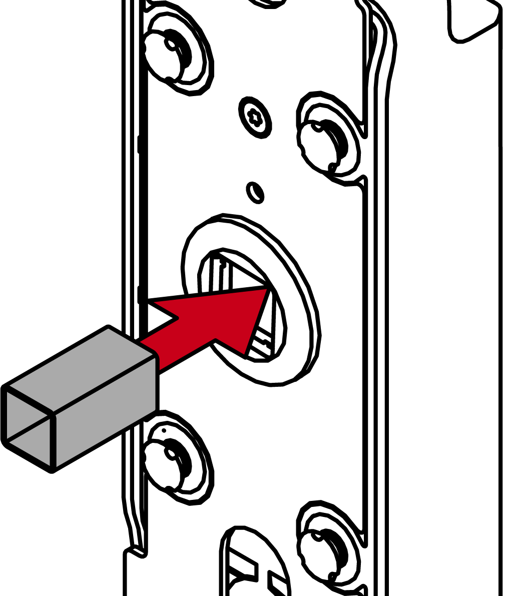
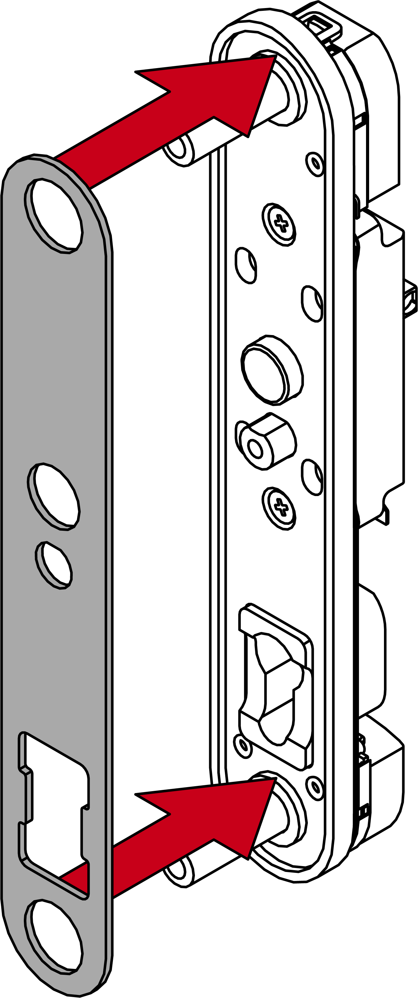
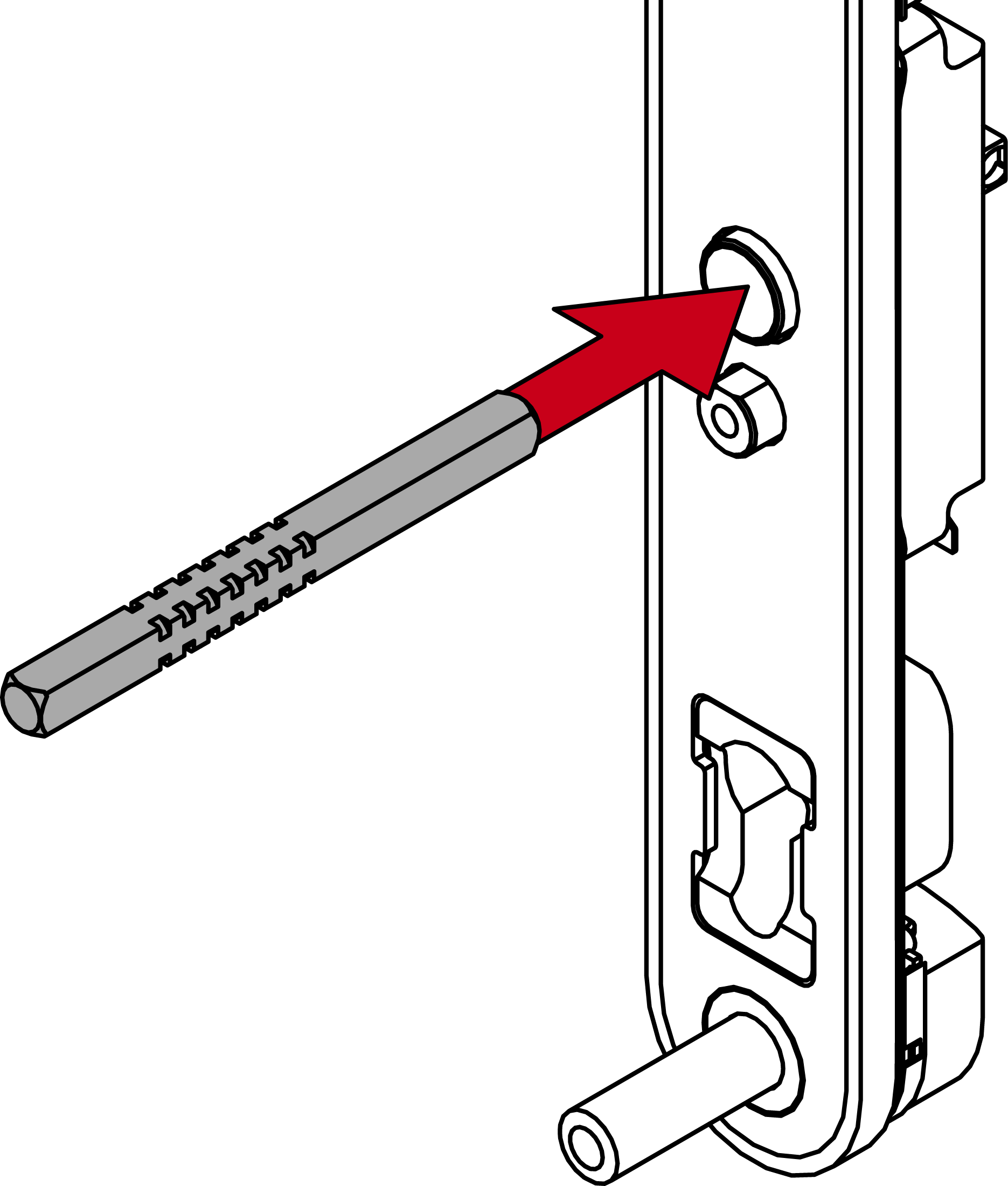
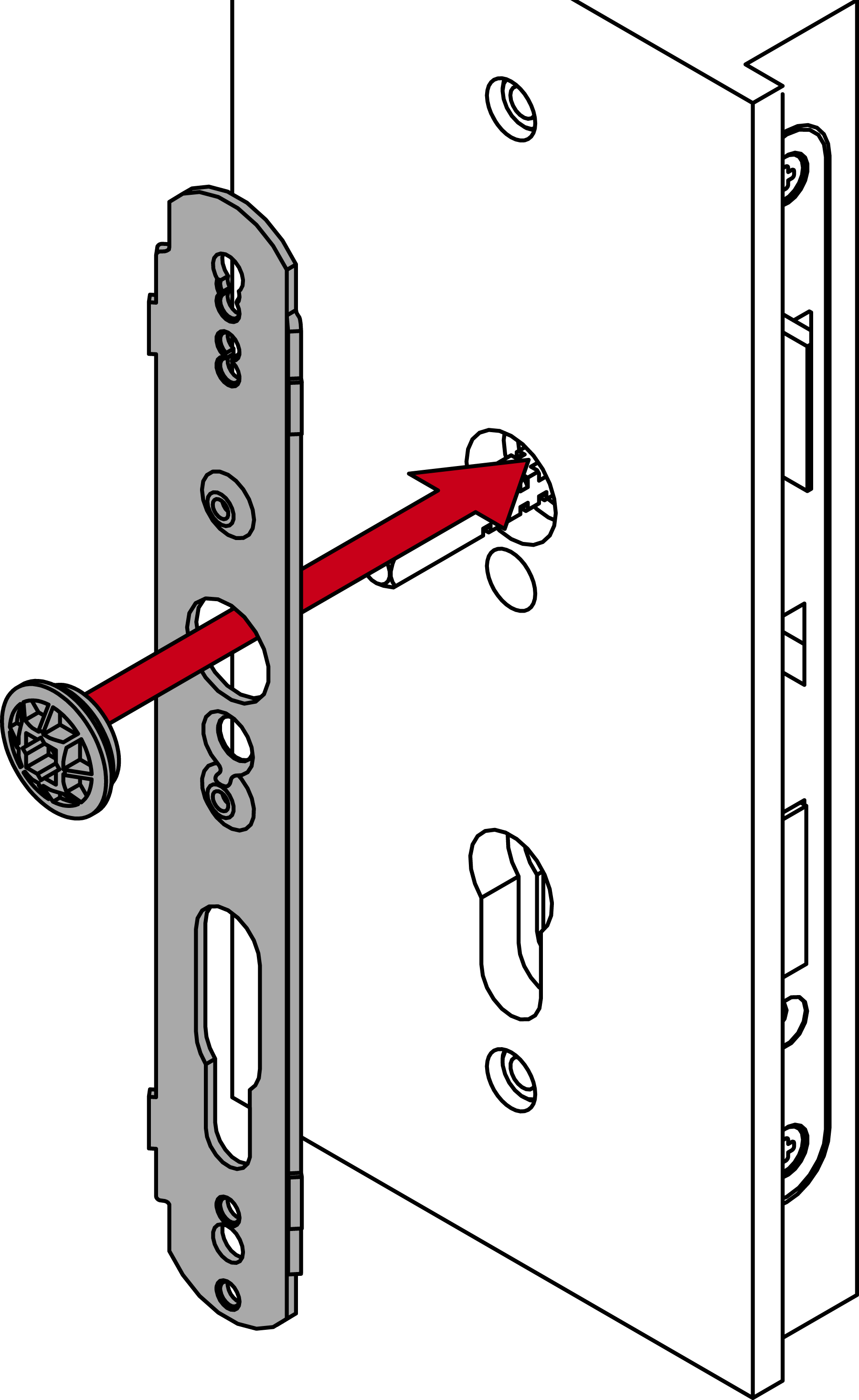
- Insert the sleeve nuts into the hardened drill protection plate.
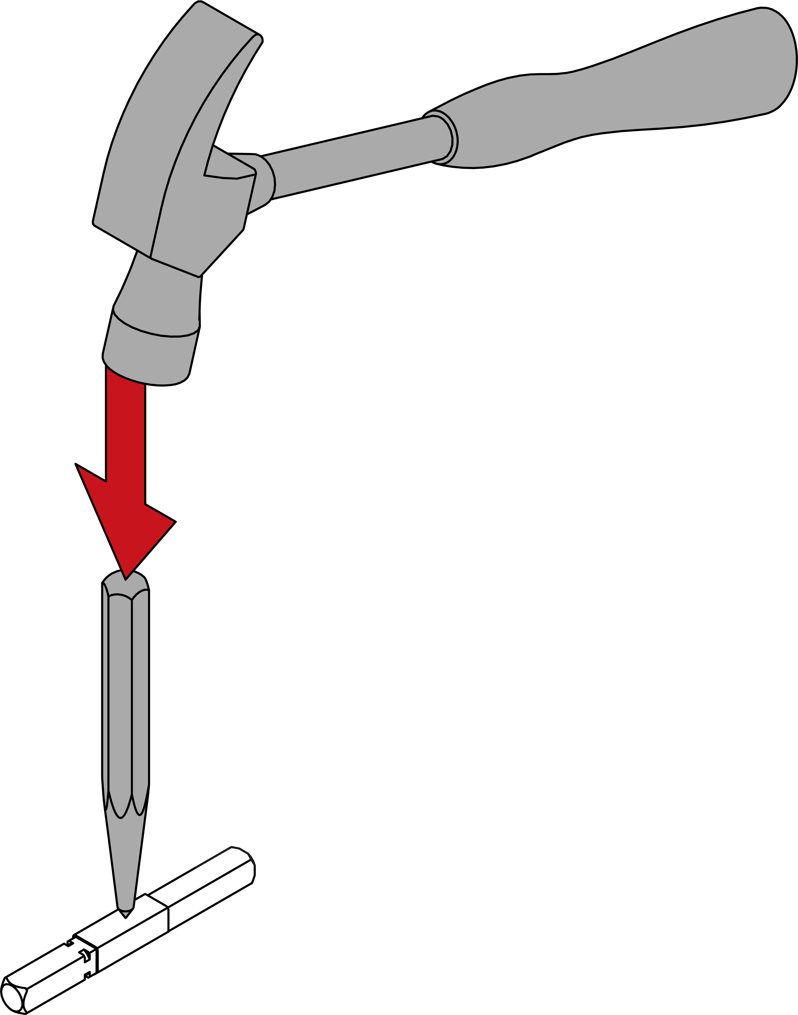
- For 8.5 mm and 10 mm spindle: slide the adapter sleeve into the centre of the spindle. Use a punch and hammer to make an indent in the adapter sleeve to prevent it from slipping.
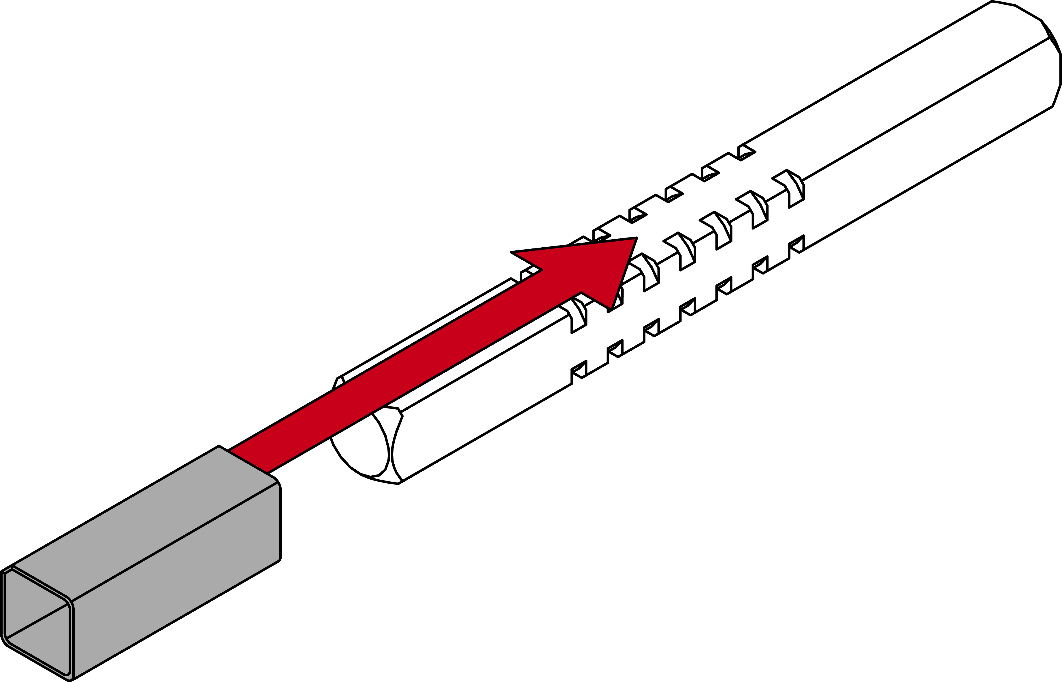
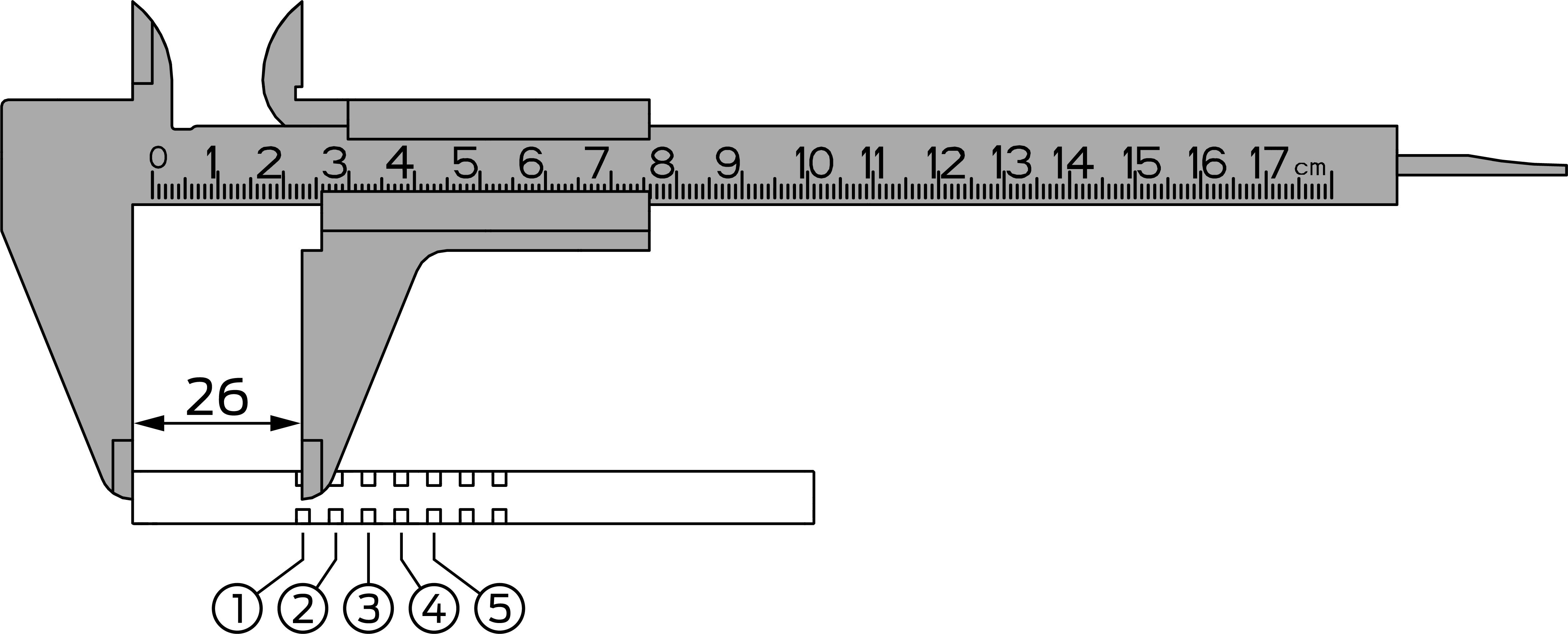
- Measure the total length of the spindle.
- Locate the inside of the spindle (four-edge end up to the centre of the first groove = 26 mm).
- Use the table to determine the position of the O-ring.
Size
Door thickness (mm)
Spindle length (mm)
Ring position
S
39 – <43
94
1
S
39 – <43
104
3
S
43 – <48
104
2
S
48 – <53
104
1
S
48 – <53
114
3
S
53 – <58
114
2
S
58 - 62
114
1
M
61 - <63
124
3
M
61 - <63
134
5
M
63 – <68
124
2
M
63 – <68
134
4
M
68 – <73
124
1
M
68 – <73
134
3
M
73 – <78
134
2
M
78 - 82
134
1
L
81 - <83
144
3
L
81 - <83
154
5
L
83 – <88
144
2
L
83 – <88
154
4
L
88 – <93
144
1
L
88 – <93
154
3
L
93 - 97
154
2
- Insert the spindle with the outer side into the fitting.
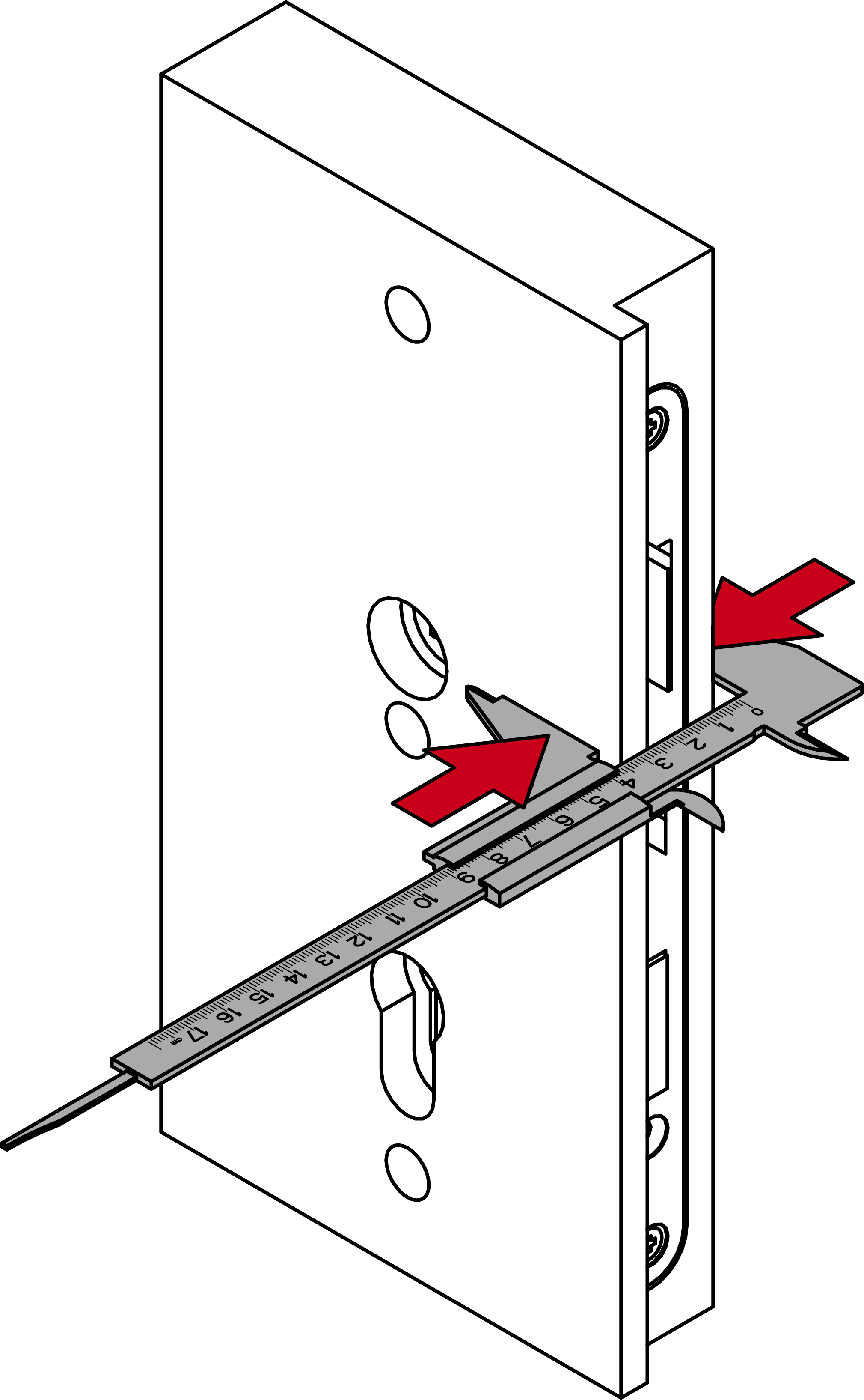
- Measure the door thickness.
Size
Door thickness (mm)
Screws (M8)
Screw (M6)
S
39 – <45
30
50
S
45 - <47
35
50
S
47 – <52
35
55
S
52 - <53
35
60
S
53 - <56
45
60
S
56 - <62
45
65
M
61 - <65
50
70
M
65 - <67
55
70
M
67 – <72
55
75
M
72 - <73
55
80
M
73 – <78
65
80
M
78 – <82
65
90
L
81 - <88
70
90
L
88 - <97
80
100
- Determine what screws are required for the door thickness measured.
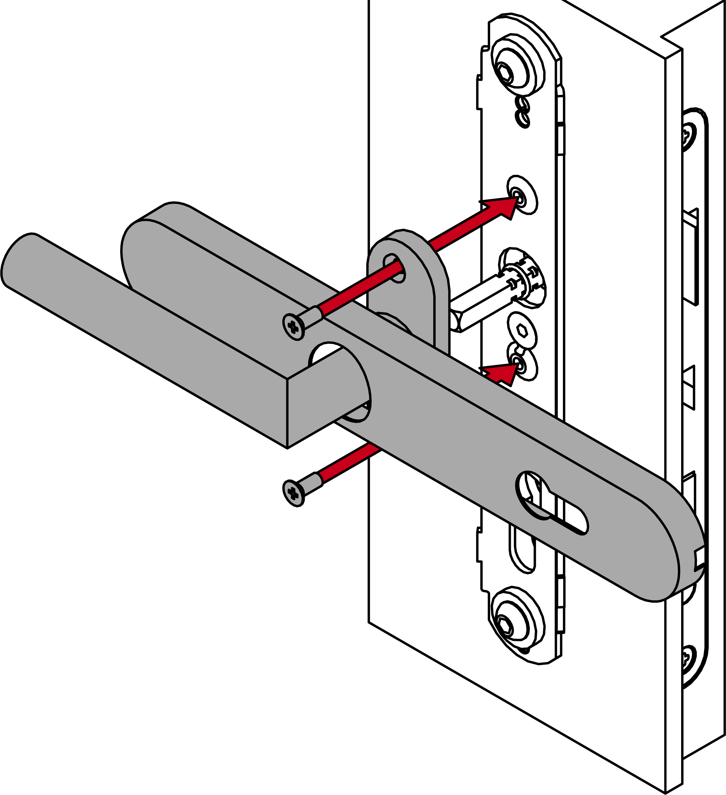
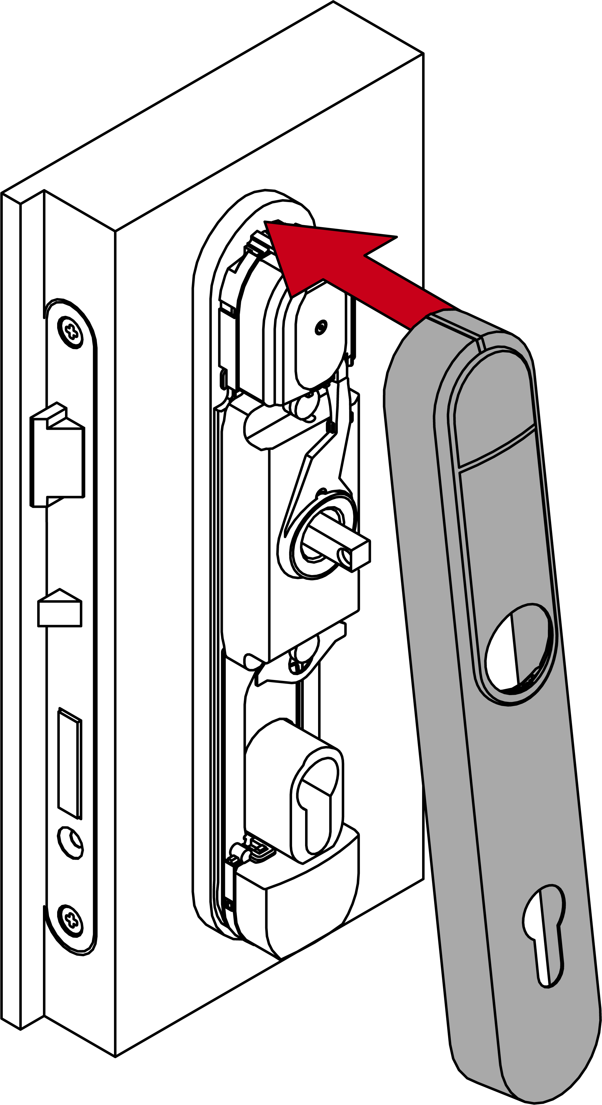
- Insert the module support with the fastening plate into the outer side of the door.
IMPORTANT
Damage to the sleeve nuts due to improper insertion
If the sleeve nut tabs are not located in the recesses, they can be damaged during further installation. In such cases, the sleeve nut can rotate unintentionally, which makes installation/removal difficult.
- Ensure that the sleeve nut tabs are located in the recesses.
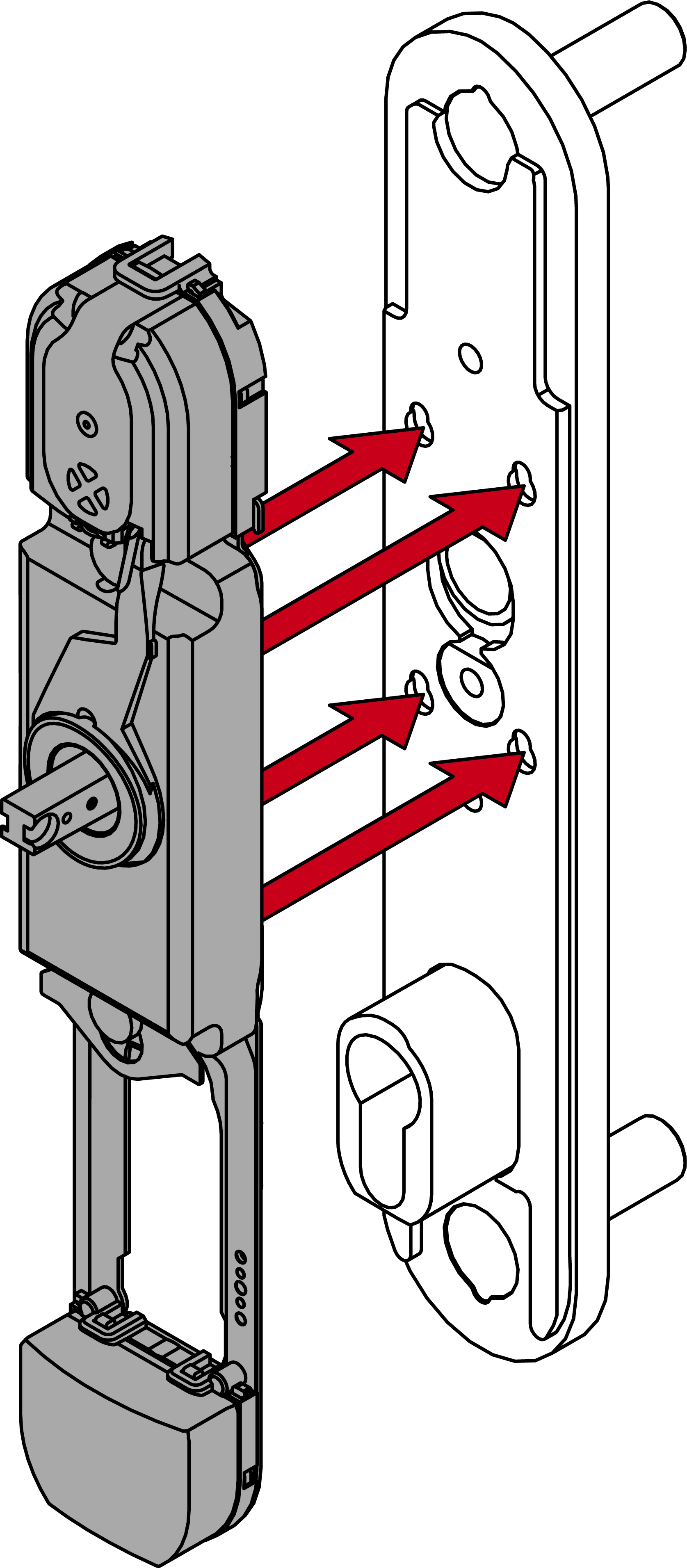
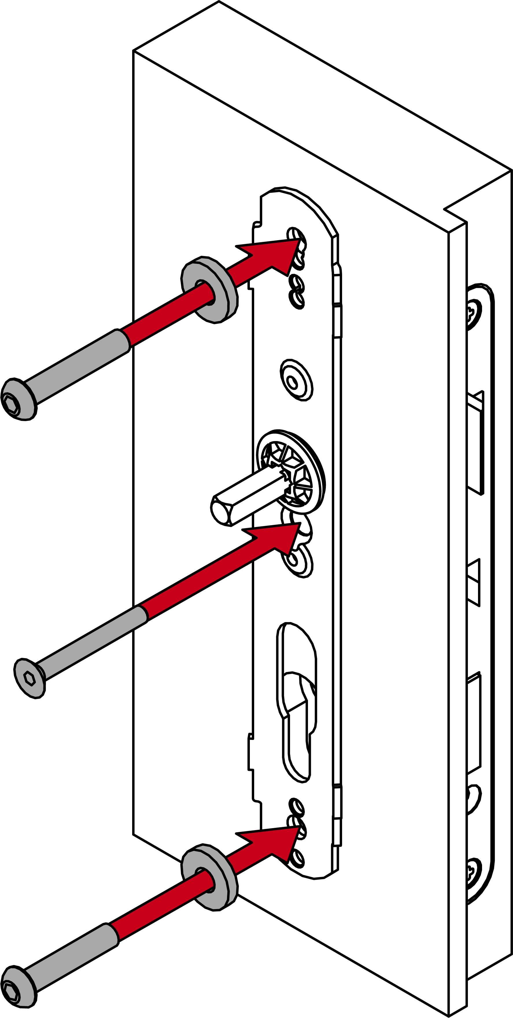
- Place the inner fastening plate and the mounting disc on the spindle.
- The mounting disc is used to align the fastening plate and the spindle with one another.
- Screw the washers and the inner plate firmly onto the module support (SW6 short screws with a torque of 5.0 Nm, SW5 long screw in the centre with a torque of 2.0 Nm).
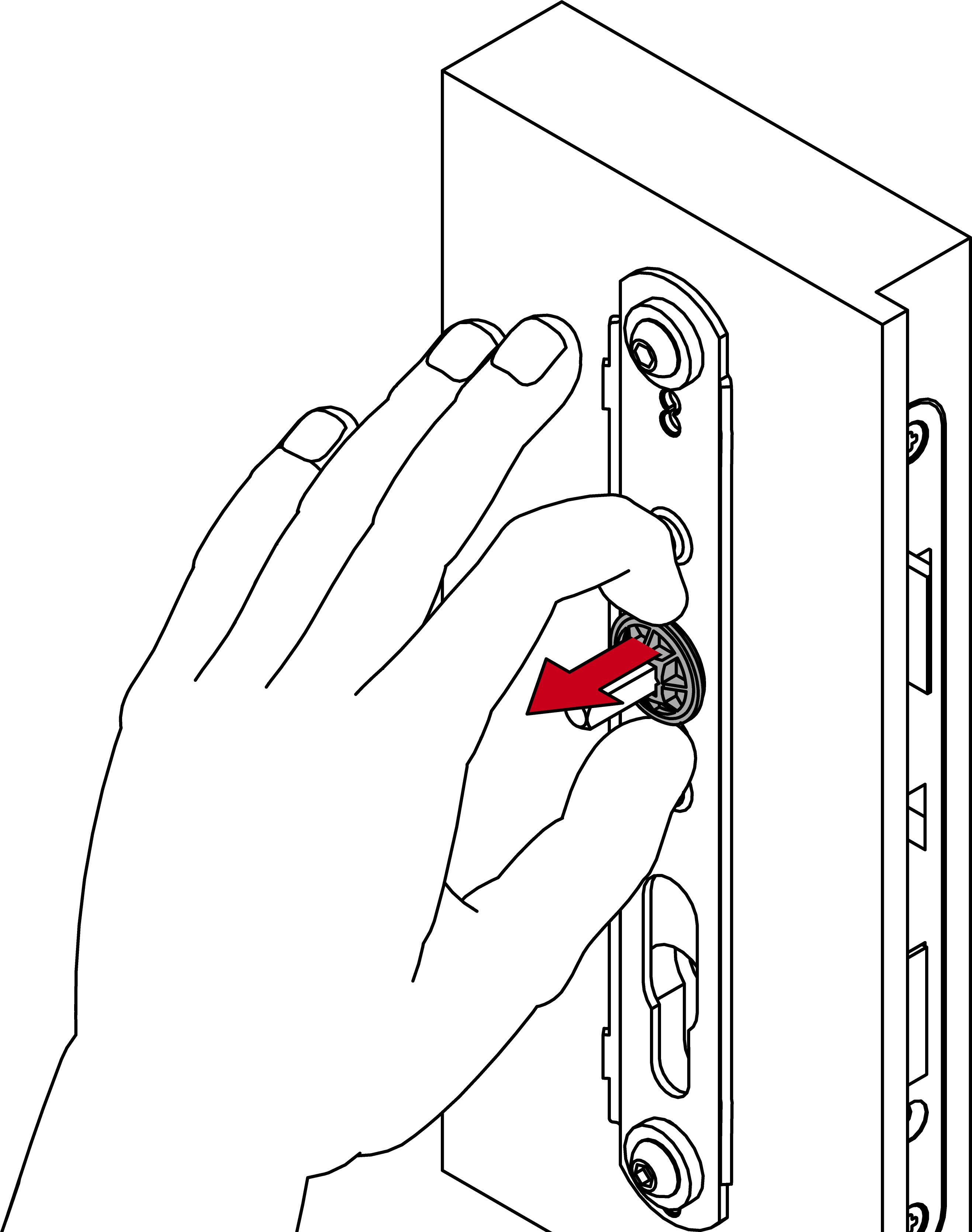
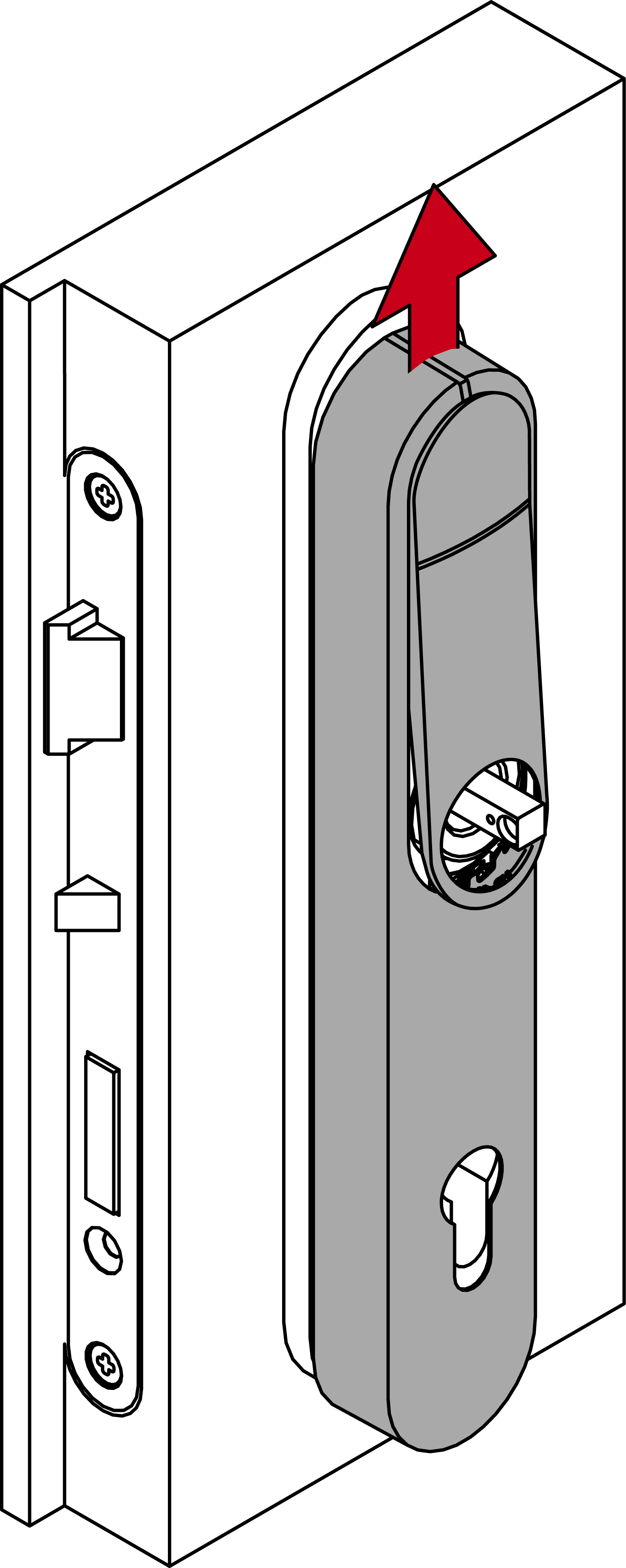
- Remove the mounting disc from the spindle again.
- Slide the O-ring onto the calculated groove.

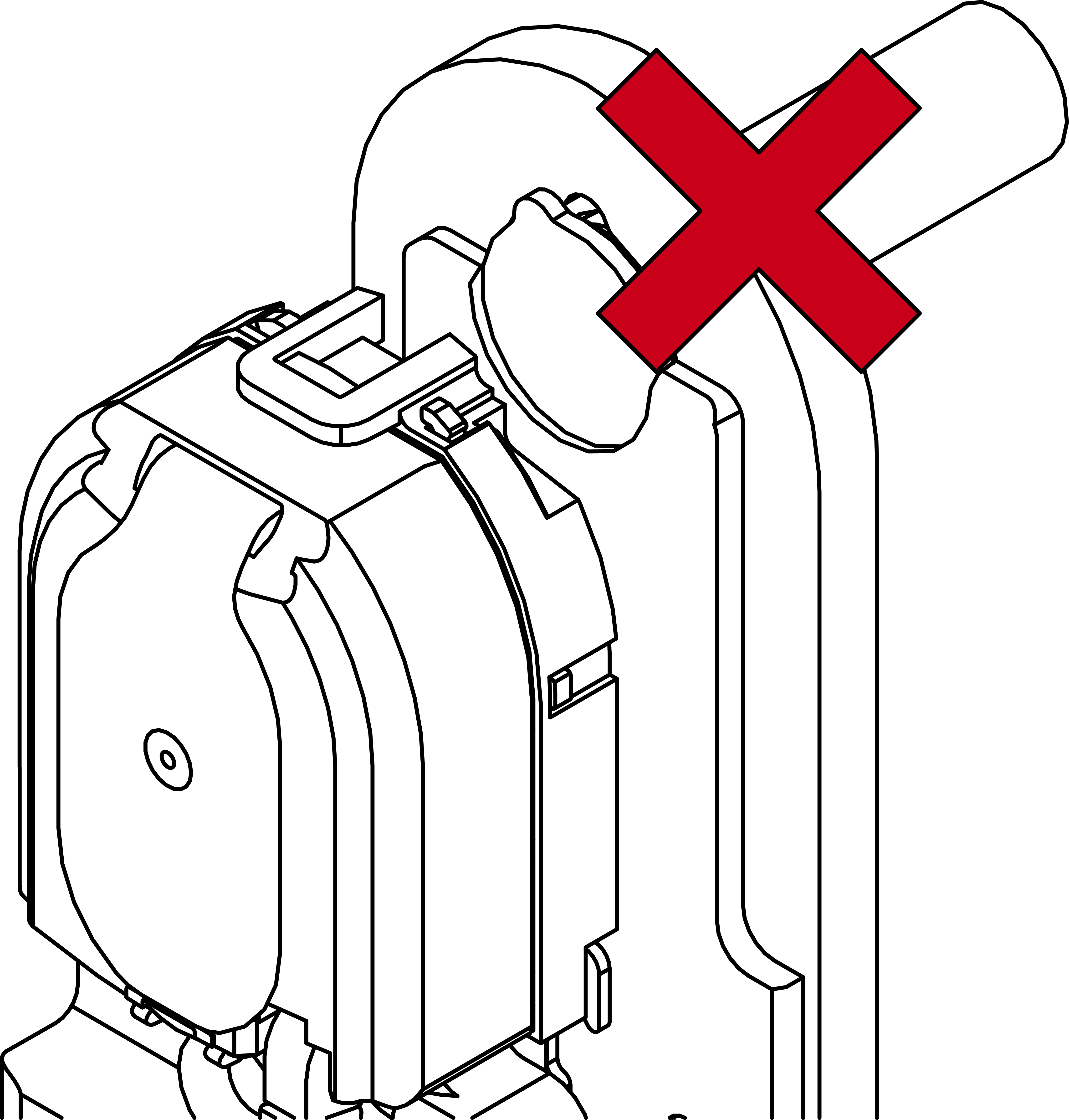
- For 7 mm spindle: Place the adapter sleeve in the inside handle in such a way that the recess faces the grub screw.
- Determine the required direction of rotation for your inside handle.
- Insert the spring element appropriately.
- When using rectangular or offset inside handles (*B, *D, *E, *F): slide the cover onto the inside handle before screwing it into place.
- Use the 12 mm screws to fix the module support onto the fastening plate (PH2; torque: 3.0 Nm).
- When using rectangular or offset inside handles (*B, *D, *E, *F): straighten the cover by turning it back into place.
- Attach the cover at the top and press it firmly until it clicks into place.
- Place the cover on top of the fastening plate.
- Fold down the cover.
- Slide the cover upwards.
- Press the inlay into place.

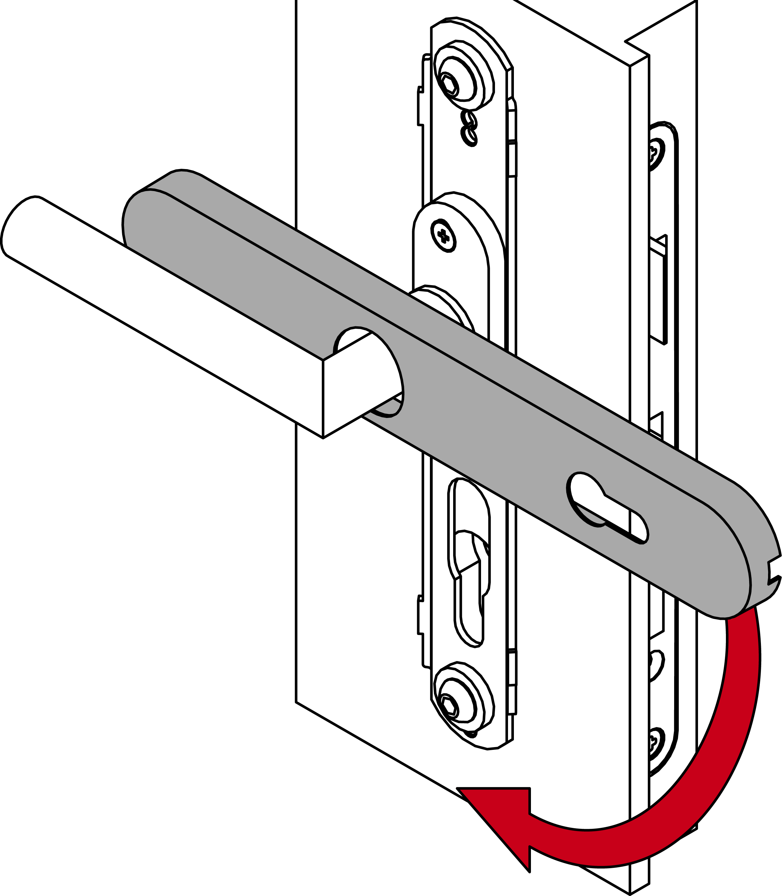
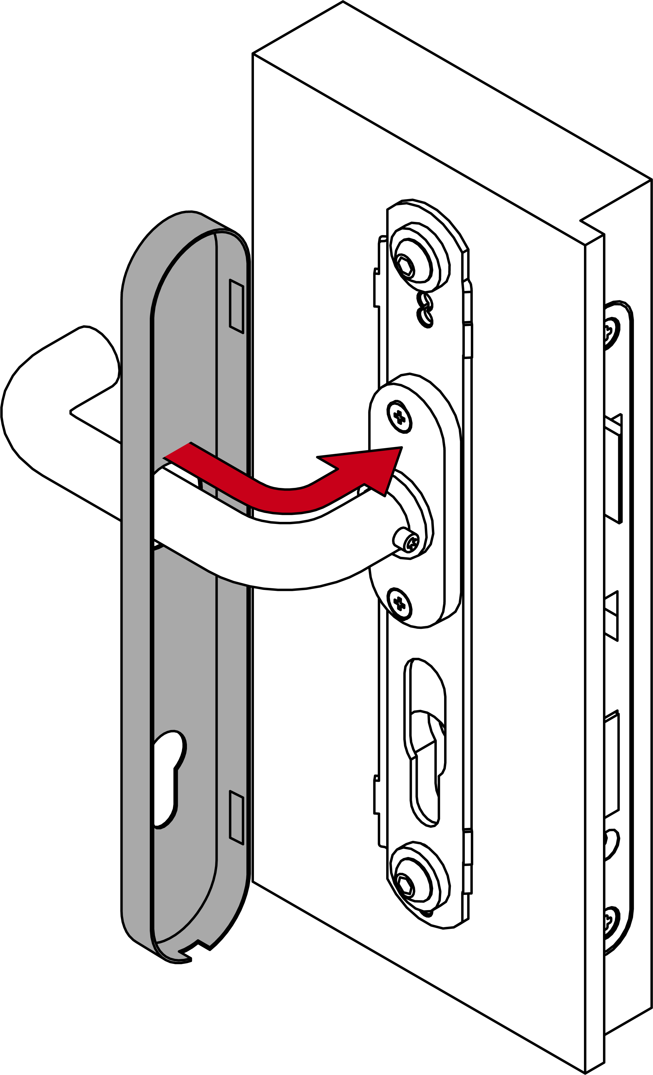
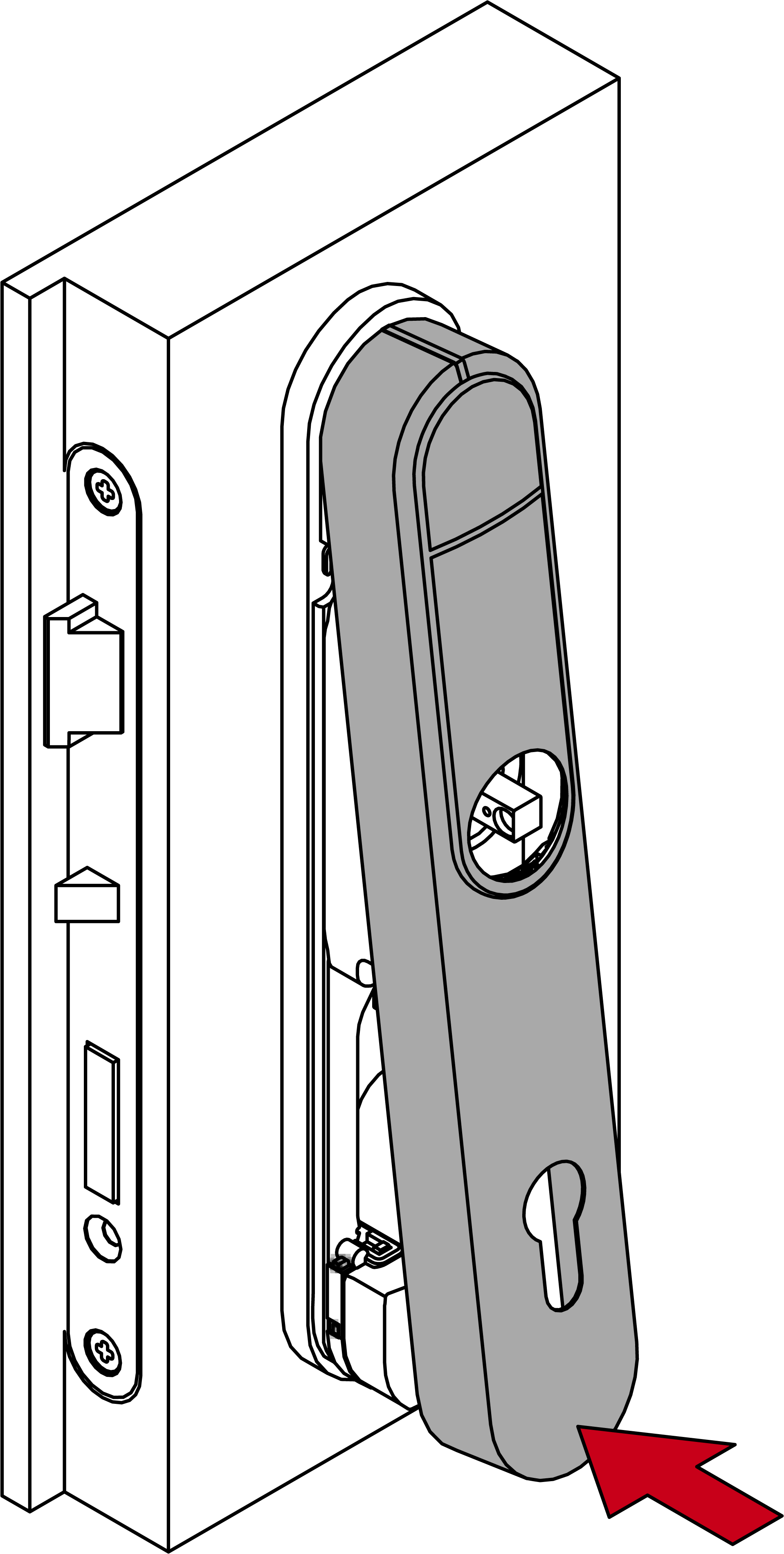
- Fit the outside handle.
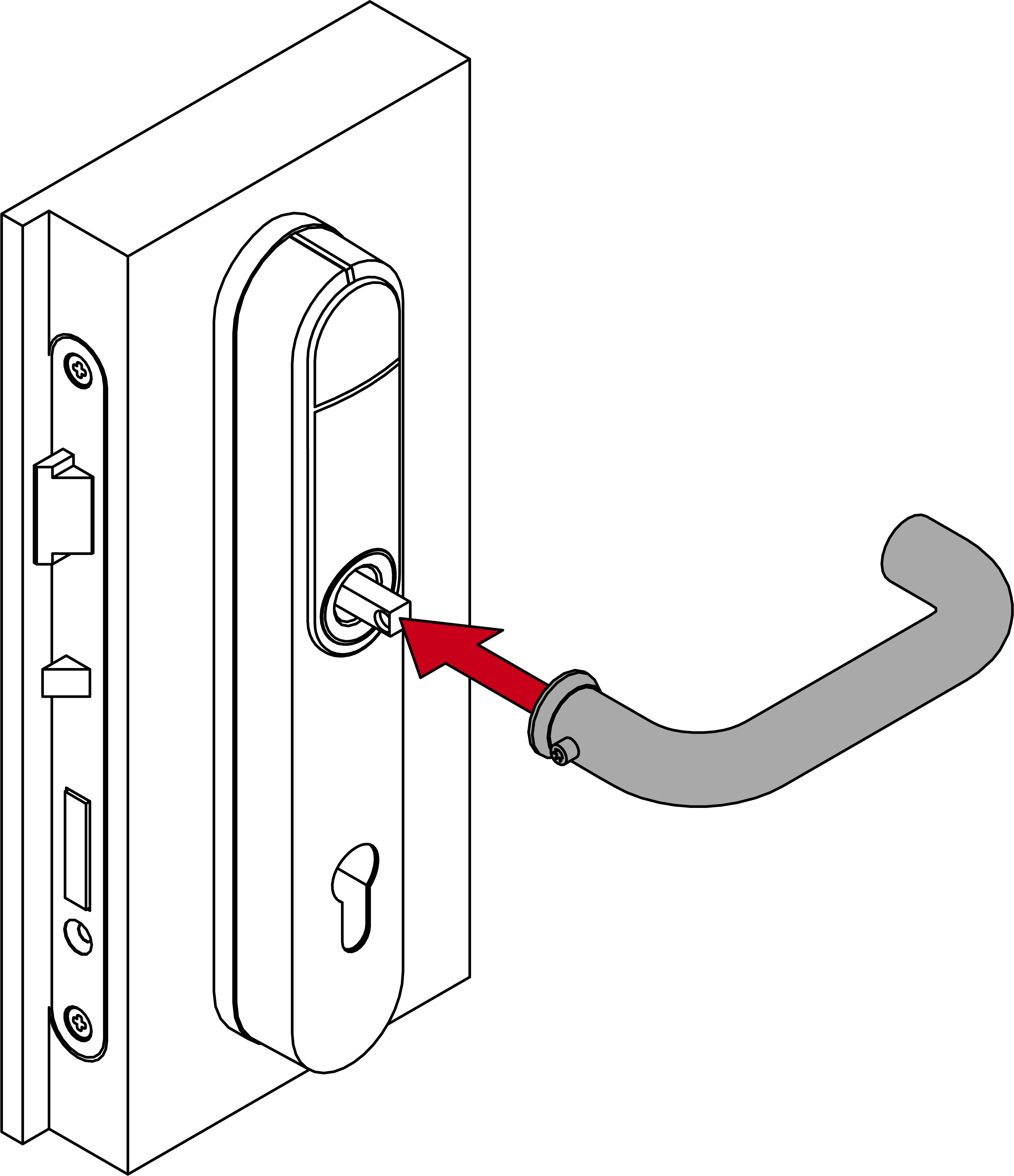
- Use the grub screws to tighten both handles (TX15, torque 5.0 Nm).

- Insert a locking cylinder.
NOTE

Requirements for the security fitting approval
The approval for the SI SmartHandle AX Advanced is subject to conditions:
- Observe the locking cylinder’s protection class.
- The locking cylinder’s housing may protrude a maximum of 3 mm above the cylinder protection profile.


- Fasten the locking cylinder with a fastening screw (PH2, torque 1.1 Nm).

- SI SmartHandle AX Advanced fully installed.
