Installation and fitting - Locking cylinder (Z4) DoorMonitoring
Installation instructions
The DM Cylinder is installed in the same way as any other SimonsVoss digital cylinder
Batteries are already installed when the product is delivered. The cylinder is ready for immediate use
When installing the digital locking cylinder, ensure that there are no sources of low-frequency interference in the surrounding area. Typical sources are:
- Switch-mode power supply units
- High-voltage power lines
- Generators
- Frequency converters
Locking cylinders should be installed at least 0.5 m from one another while SmartRelays or activation units should be 1.5 m from one another
The locking cylinder housing may only project a maximum of 3 mm from the door in outdoor areas; a profile cylinder escutcheon or fitting should be used if necessary
You must not strike the thumb-turns when installing the cylinder
NOTE

The DoorMonitoring Cylinder must not be fitted with conventional fastening screws
Conventional fastening screws may permanently damage the cylinder
- The DM Cylinder must be fitted with a fastening screw especially manufactured for the cylinder
- The fastening screw is not included in the supply package and must be ordered separately
The standard fastening screw is available for a backset between 25 mm and 110 mm at 5 mm increments. You must indicate the lock backset when you order. If you use a fastening screw which is too short, the screw will not be able to provide a firm grip; if you use one which is too long, you cannot screw it fully within the door leaf
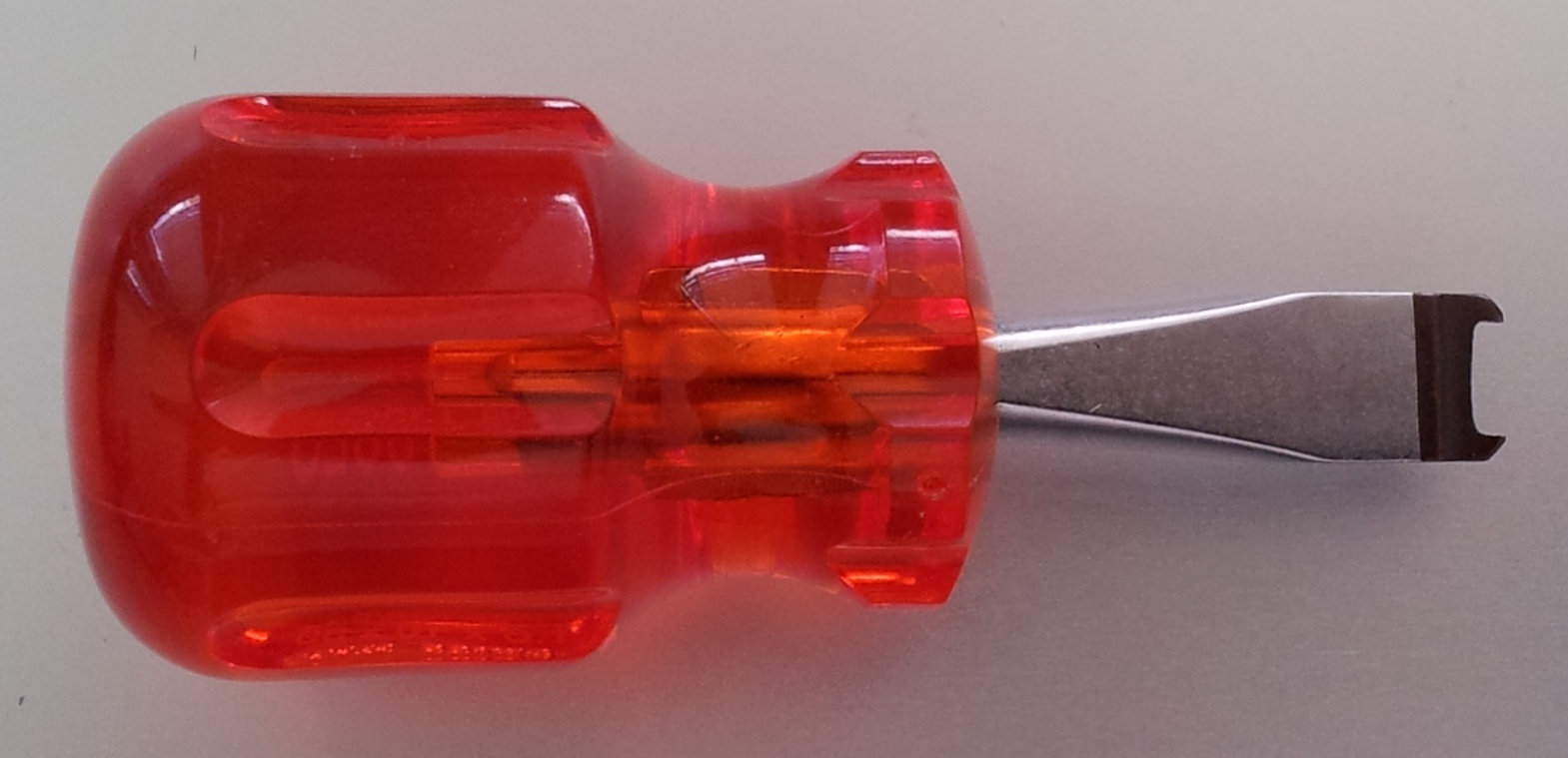
The head of the fixing screw features a sensor. The screw is tightened using a special screwdriver or adapter. If a conventional slot screwdriver is used, it could permanently damage the screw and the sensor
Lock standards specify that the hole diameter for the fastening screw must be at least 5.4mm. Some locks are supplied with a smaller drill hole. If this is the case, you can make it larger with a 5.5-mm steel drill bit
Installation
There is a thumb-turn with electronics and a thumb-turn without electronics in digital locking cylinders. The thumb-turn electronics must be removed for installation. The electronics thumb-turn is on the inside for almost all cylinders. The few exceptions are:
- Comfort Cylinder: .CO
- Swiss Round Cylinder: .SR
The word 'IN' is engraved on the cylinder body on inside of the cylinder
The thumb-turn without electronics is merely attached in position when delivered and can be easily removed
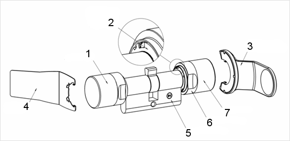
- Outside thumb-turn (without electronics)
- Locking disc with opening
- Installation and battery key
- Installation key (not for battery replacement)
- Side marking
- Recessed grip ring
- Inside thumb-turn (with electronics)
- Remove the thumb-turn without electronics
- Insert the cylinder through the lock
- Fasten the cylinder with the appropriate fastening screw. Do not fasten screw tightly. Use the correct screwdriver only
NOTE
If you tighten the fastening screw too firmly, this may cause the locking cylinder to malfunction in the lock (e.g. it may jam).
Tighten the fastening screw firmly by hand (max. 3.5 Nm)
Do not use a battery-operated screwdriver
NOTE
A conventional screwdriver can damage the sensor in the fastening screw
Tighten the fastening screw with the appropriate screwdriver only
- Replace the thumb-turn and rotate until the thumb-turn grips into the indents in the flange
- Place the installation key on the outer thumb-turn in such a way that the two teeth lock into the outer thumb-turn; if necessary, turn the thumb-turn until both teeth engage into the locking disc
- Lock the thumb-turn into position again by rotating it 30° in a clockwise direction