Installation - SmartLocker AX
The adapter plates are not used for wooden doors. Use the supplied fastening pieces.
You will need the following tools:
- 0.9 mm hex wrench (included)
- Electronics needle-nosed pliers
- PH1 screwdriver
- Slotted screwdriver (if the dead-bolt block needs to be replaced)
- 2.5 mm hex wrench
- TX10 screwdriver
- SmartLocker AX locked ex works = dead bolt extended, programme if necessary (see Programming.
- Door and parts calculated (see Measurement and calculation).
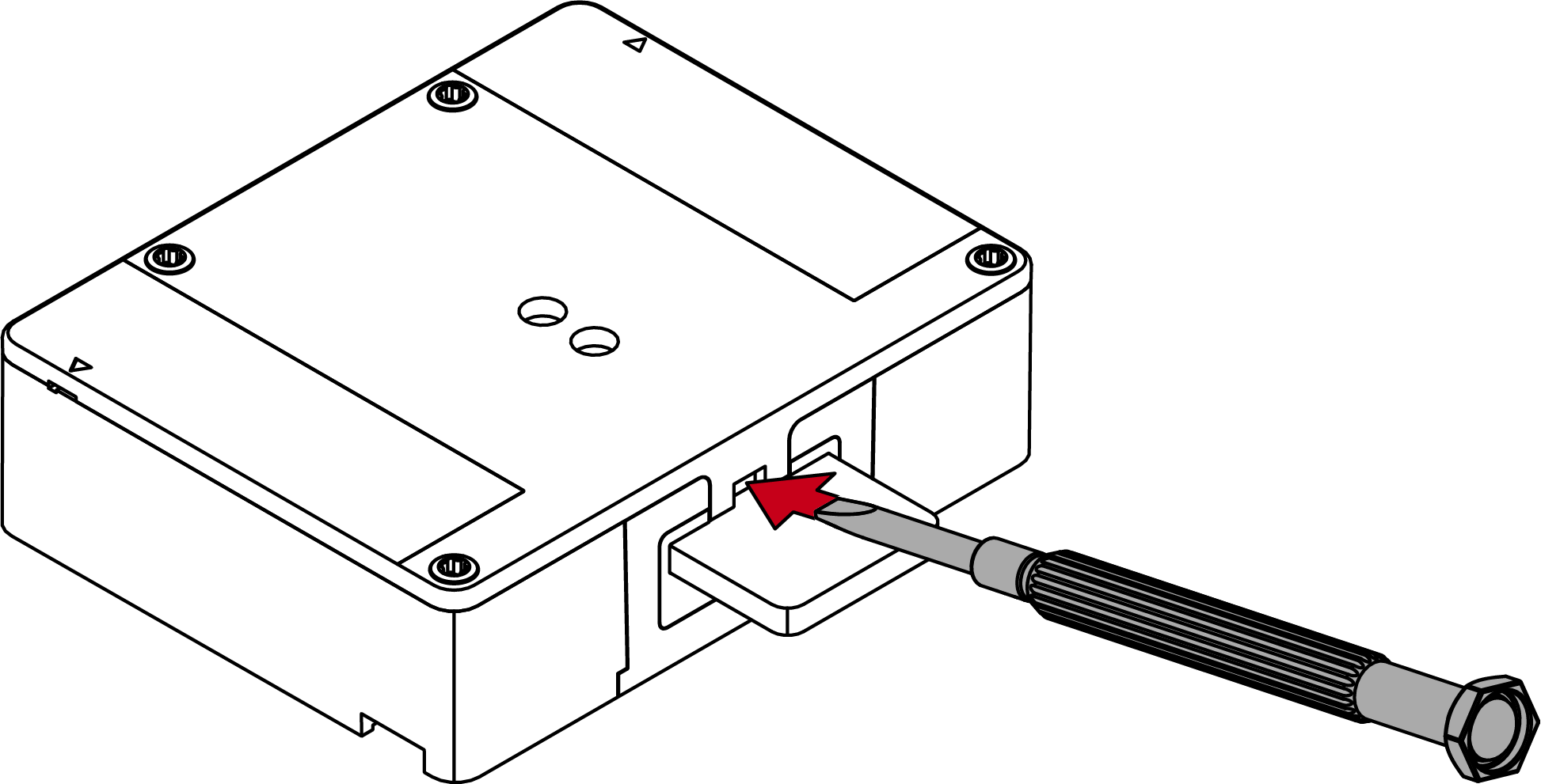
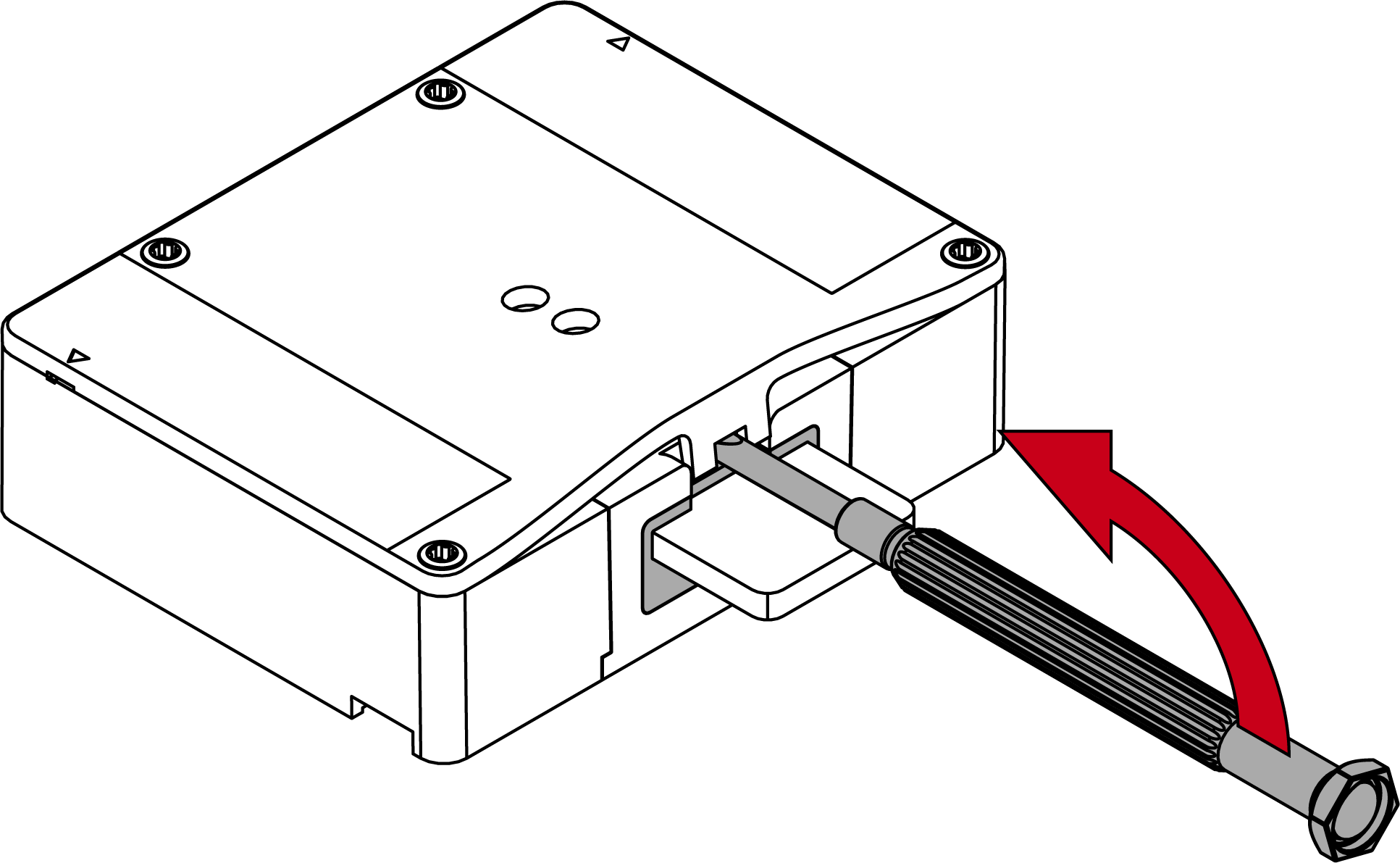
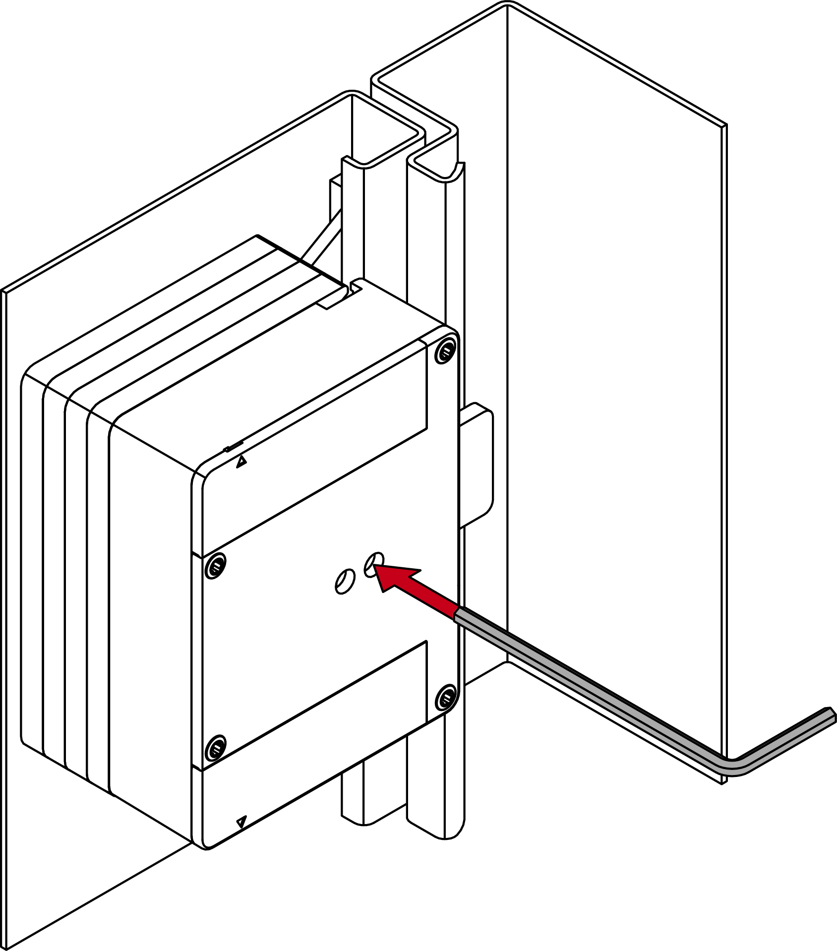
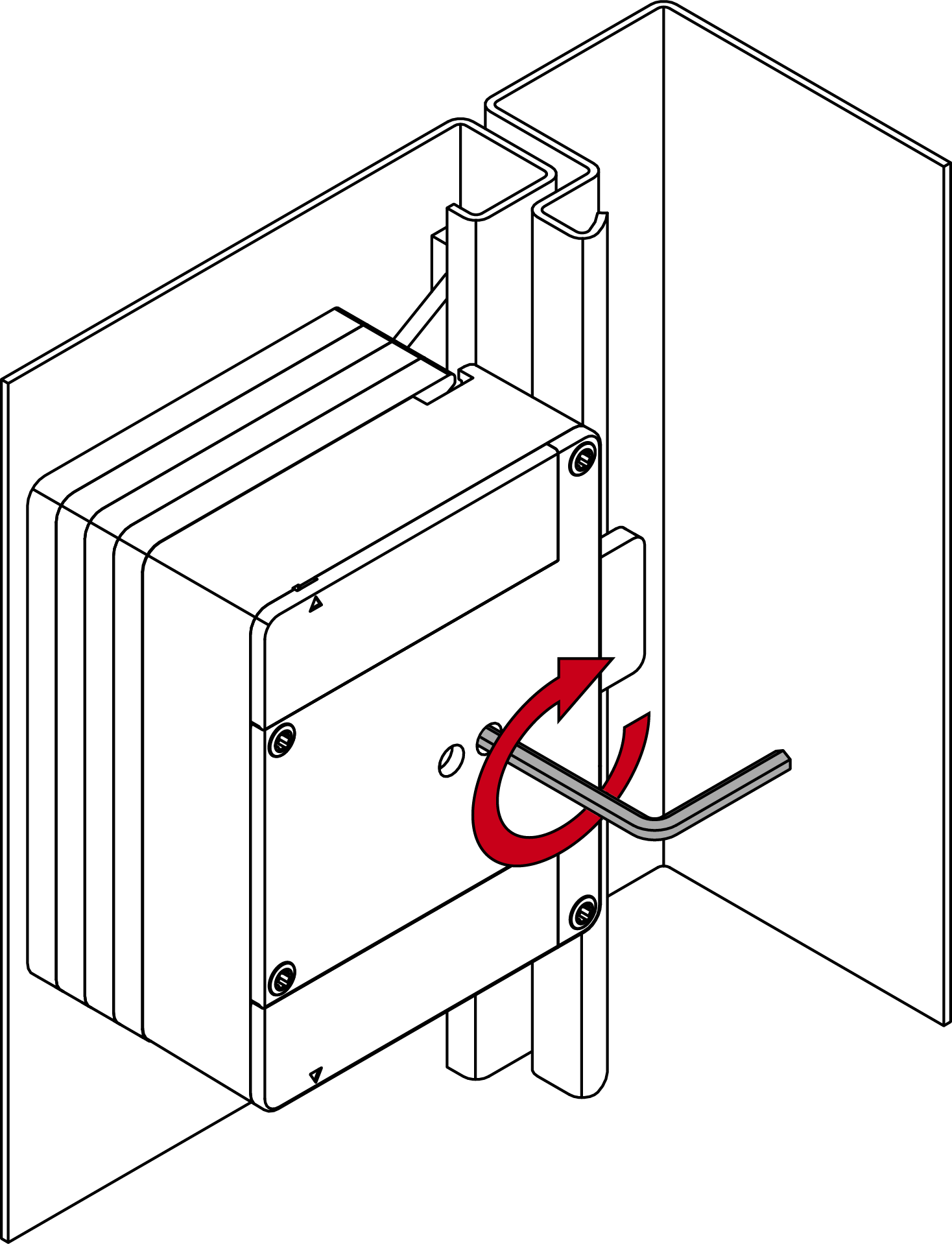
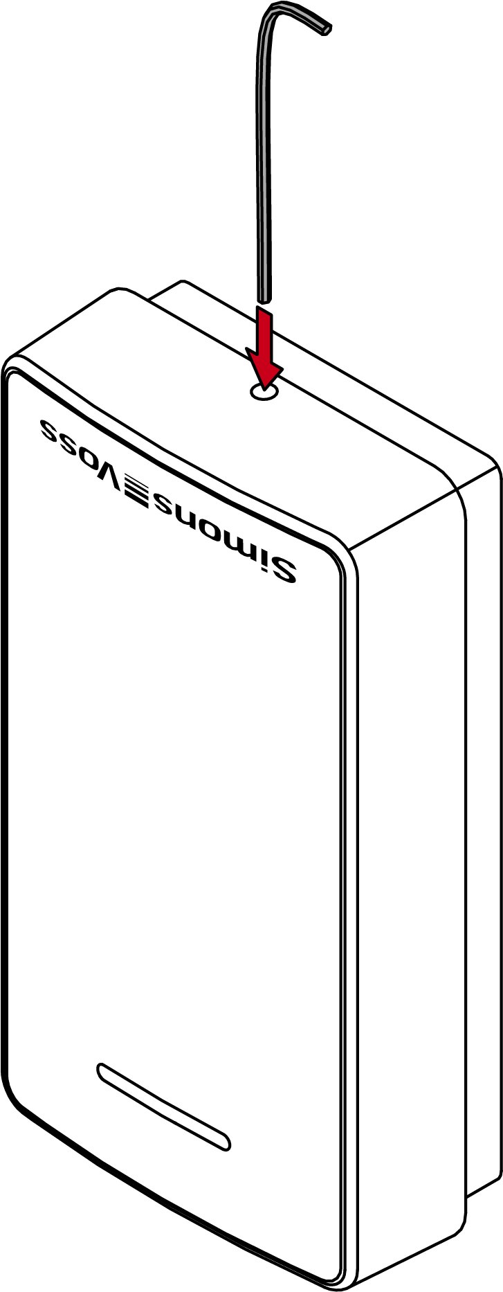
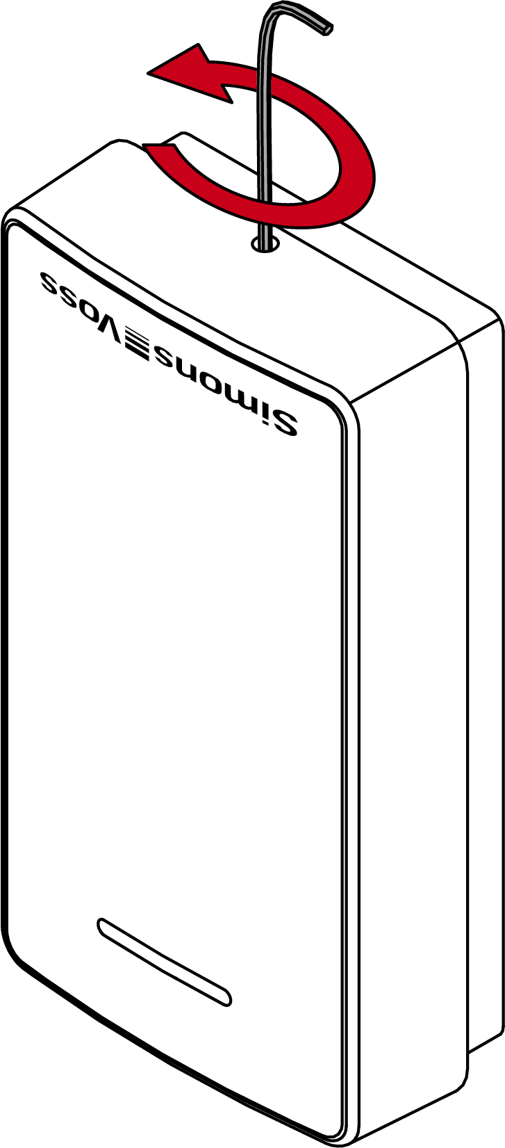
- Insert the 0.9 mm hex key into the lower screw.
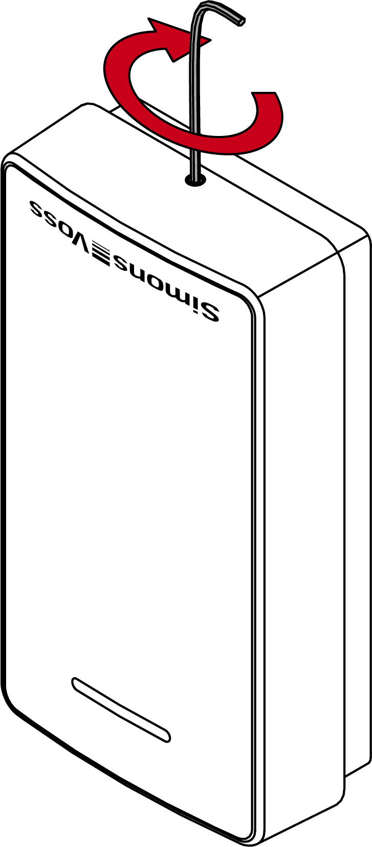
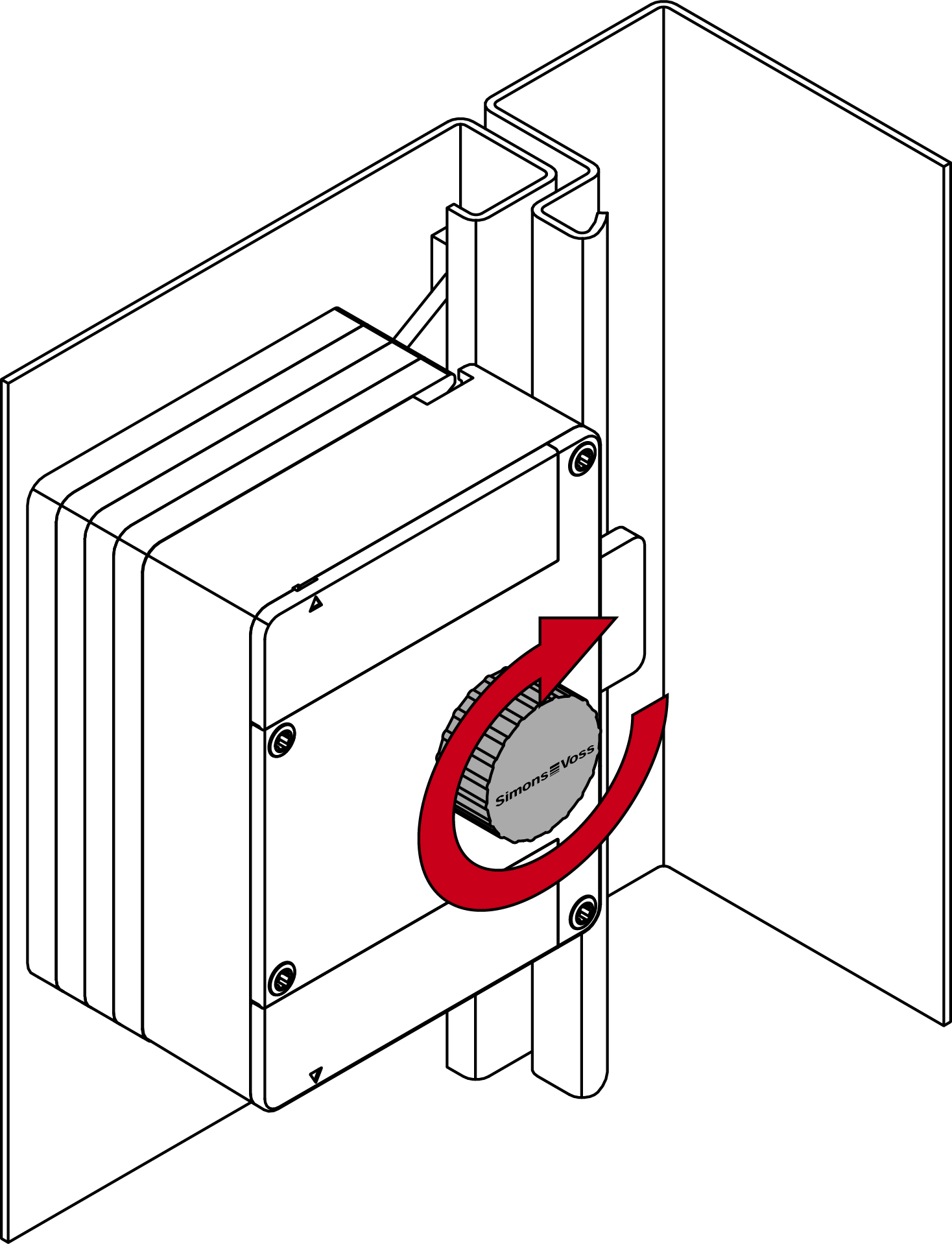
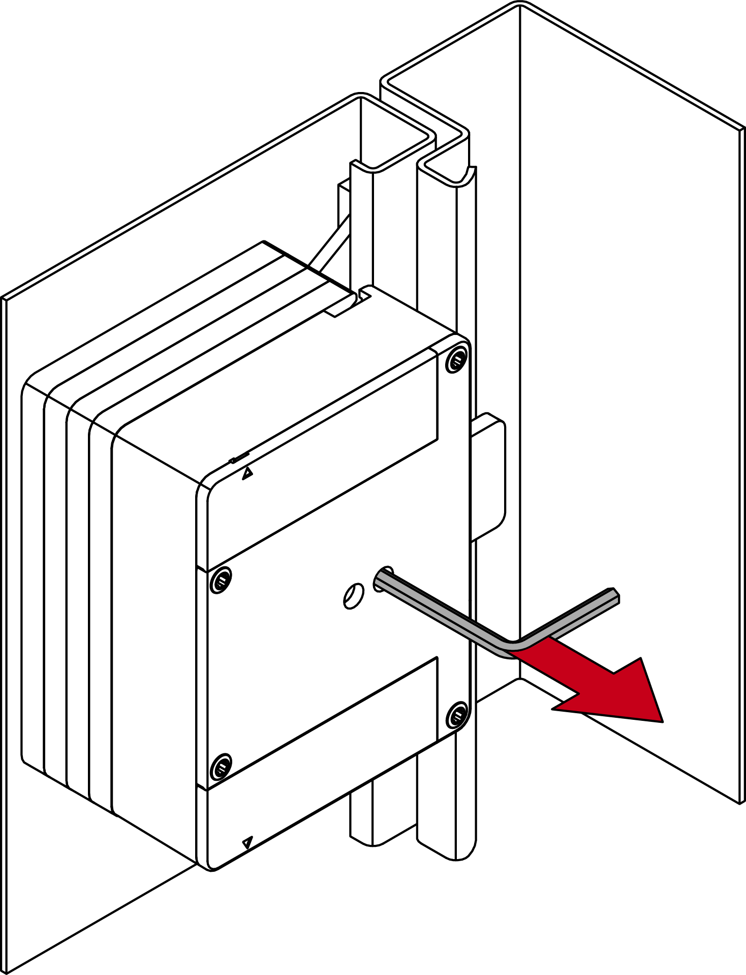
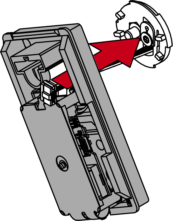
- Gently press the reader cover against the floor and turn the lower screw clockwise inwards until you can lift off the cover.
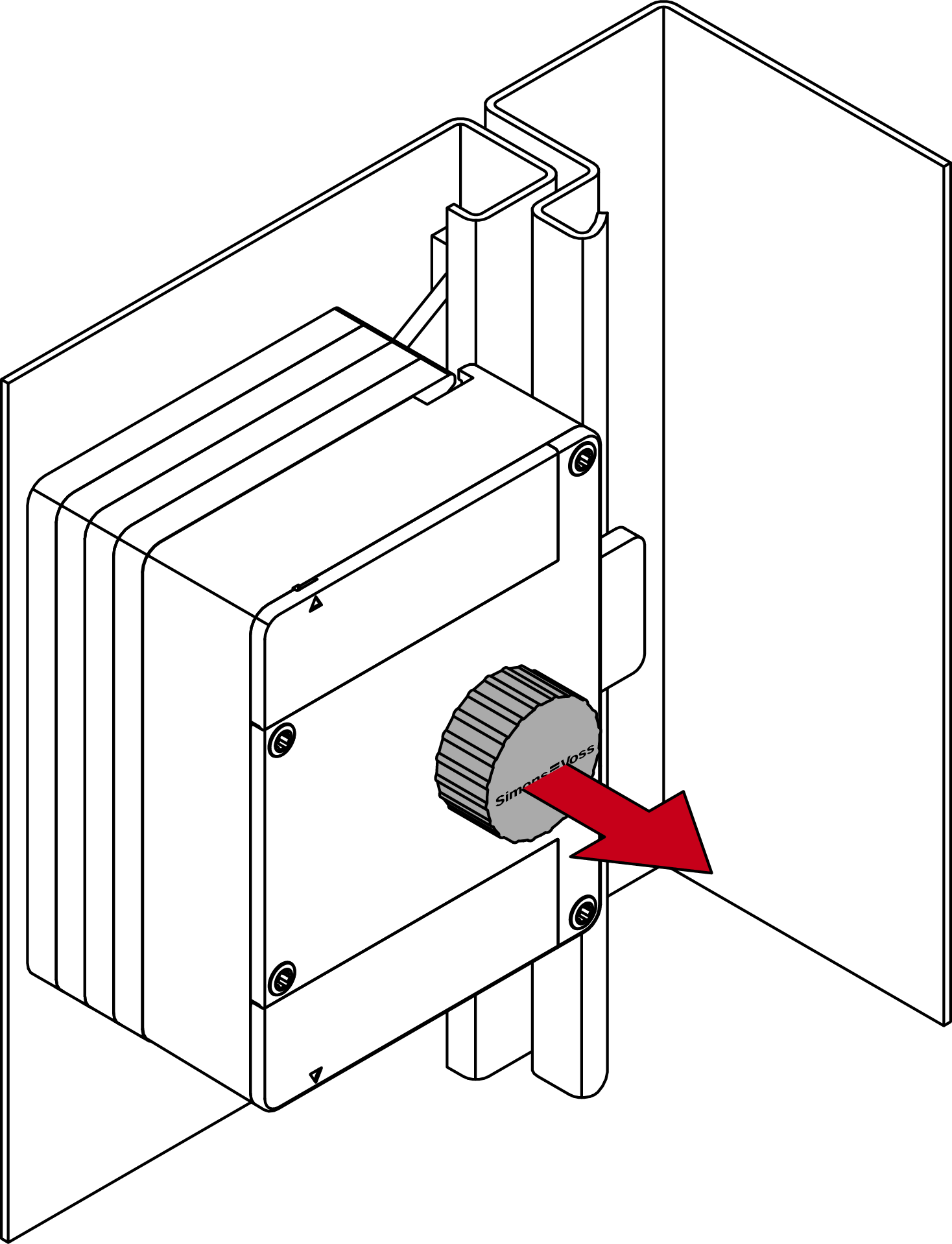
- Remove the cover.
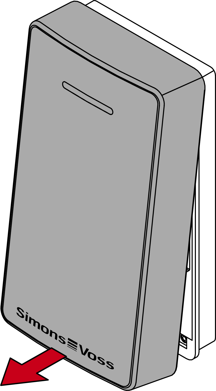
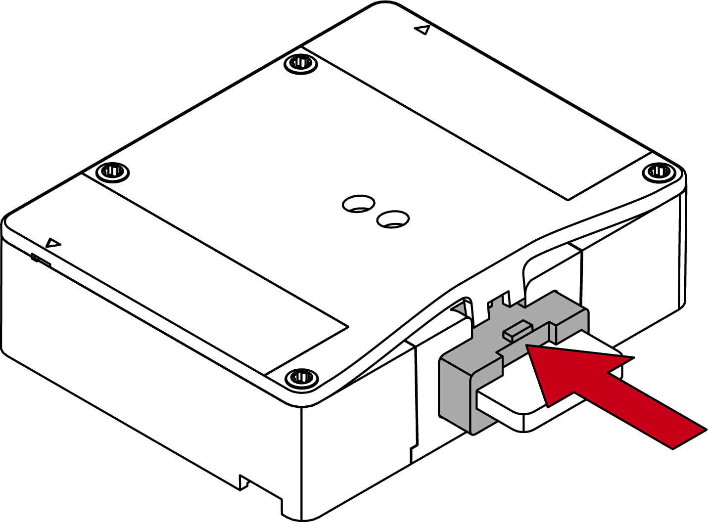
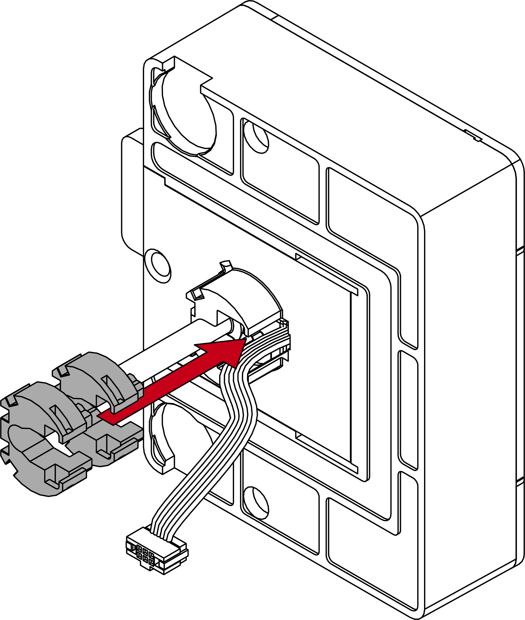
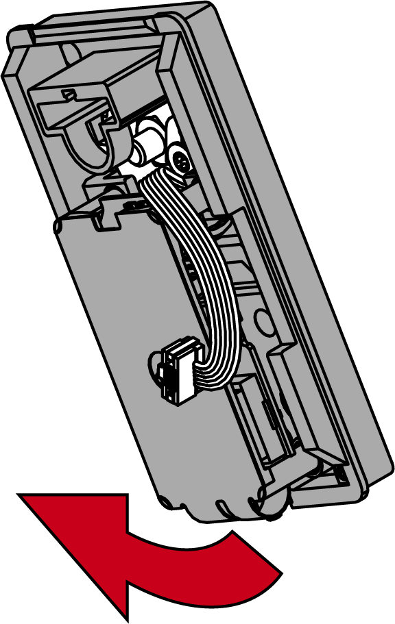
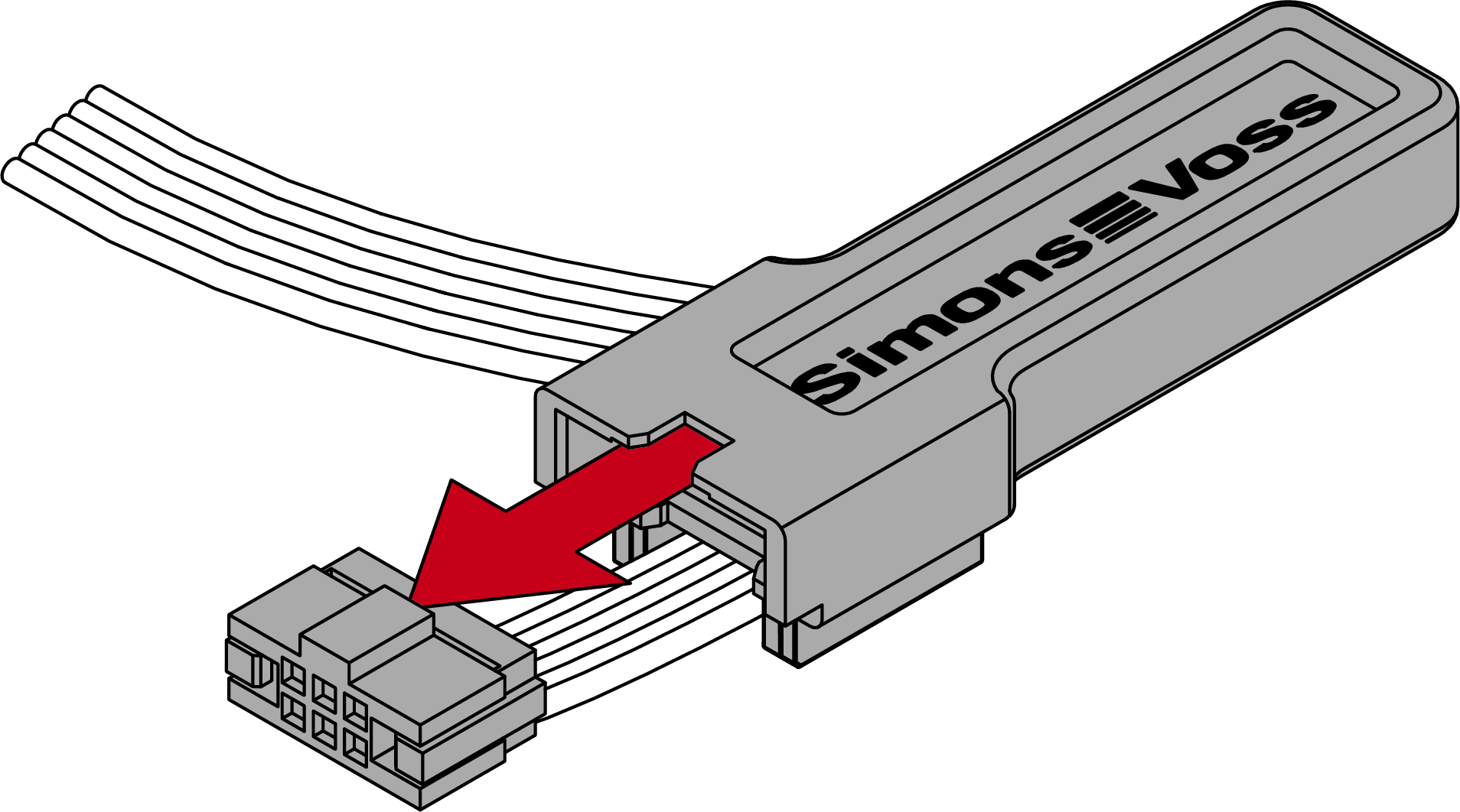
- Using needle-nosed pliers, disconnect the plug of the cable below the circuit board.
- Disassemble the reader and engine block.
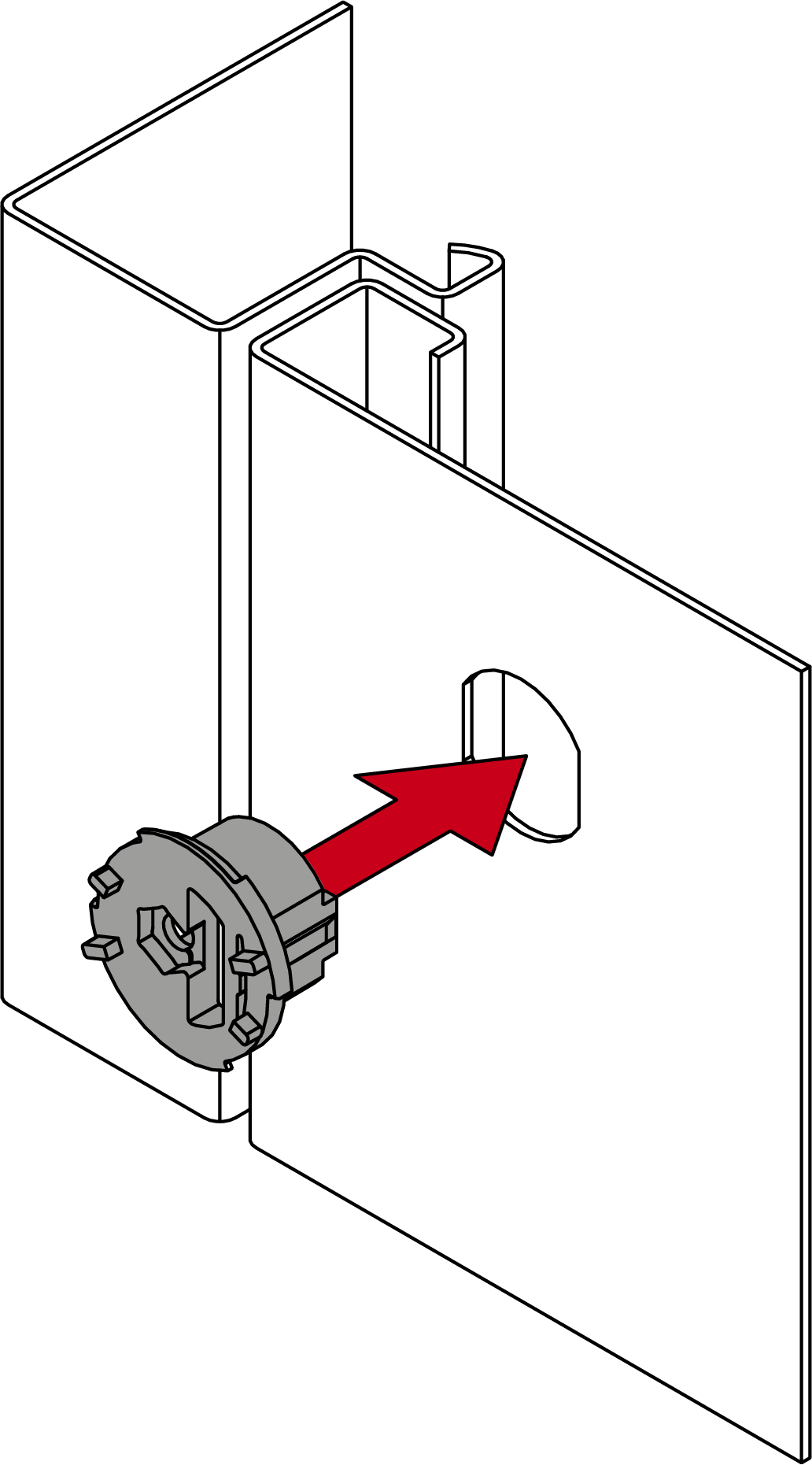
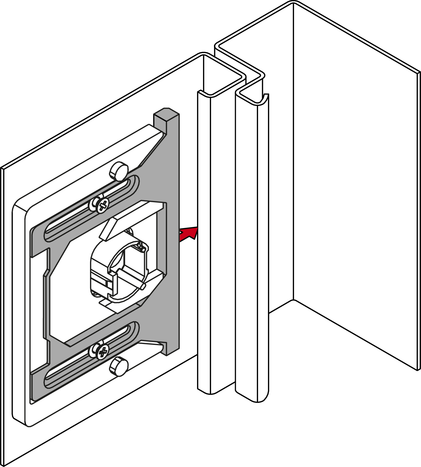
- Insert the socket into the D-hole (mount for nut pointing towards the edge of the door).
- Insert the adapter plate with the parallel forced guide onto the socket from the rear.
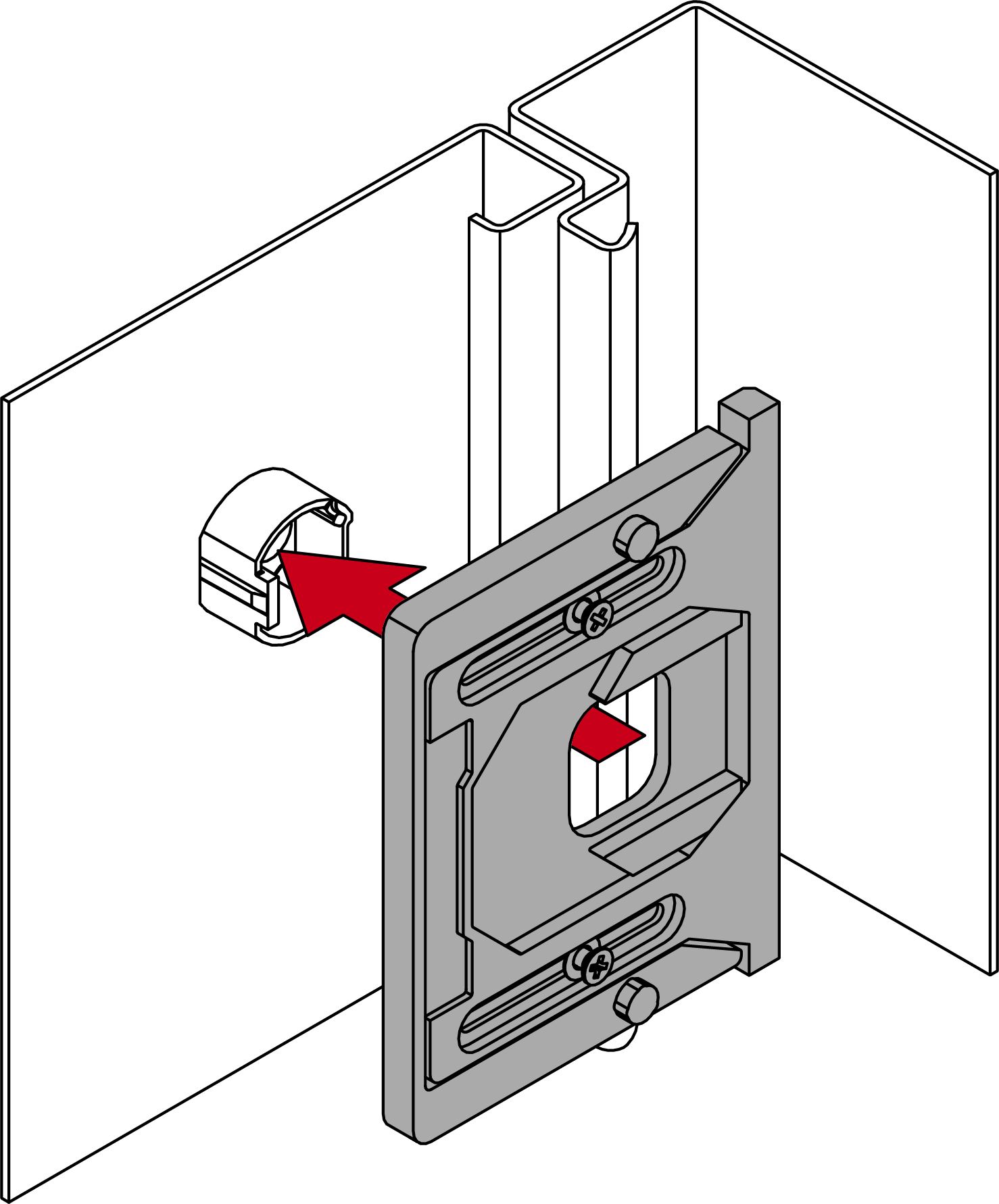
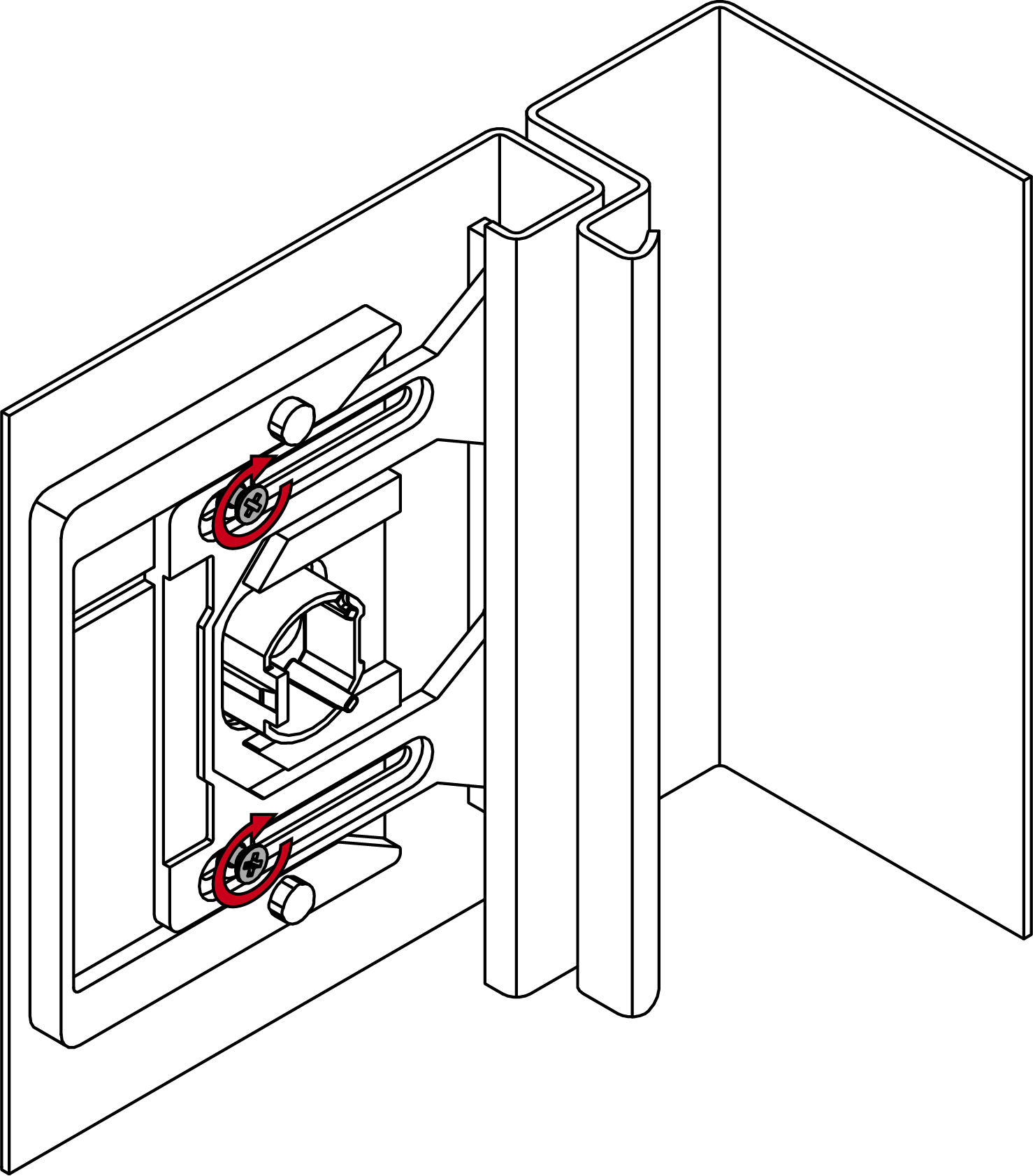
- Slide the forced guide out until it rests against the inner edge of the door.
- Continue to press the forced guide against the inner edge and screw the screws tight with approx. 20 Ncm (PH1 screwdriver) until the forced guide can no longer be moved.
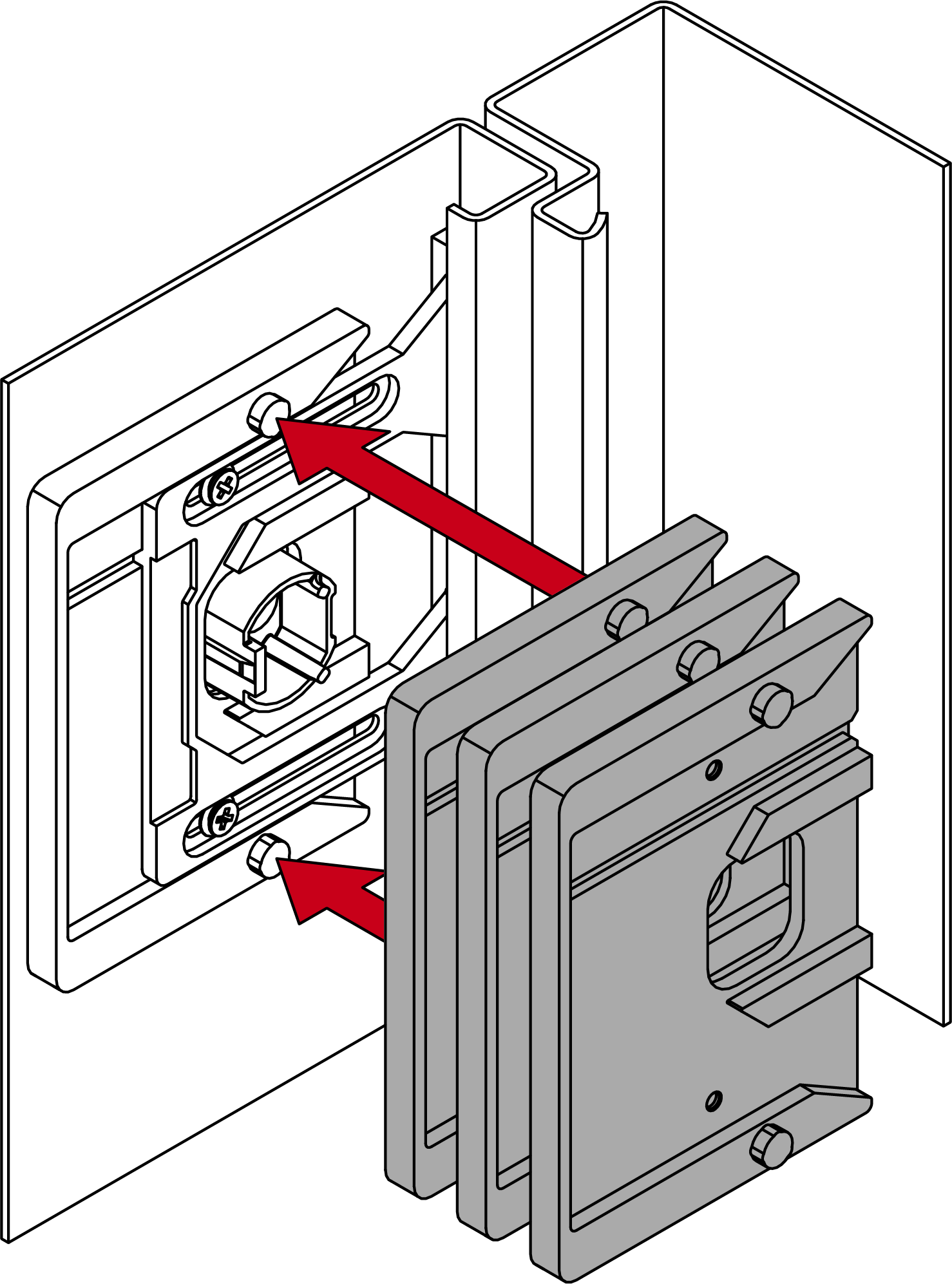
- If necessary, insert additional adapter plates into the socket.
- If necessary, lever the dead-bolt block out of the engine block using a slotted screwdriver.
- If necessary, insert another dead-bolt block into the engine block.
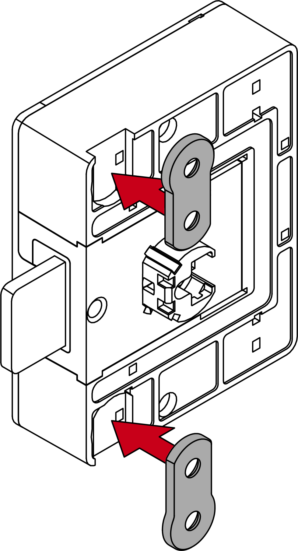
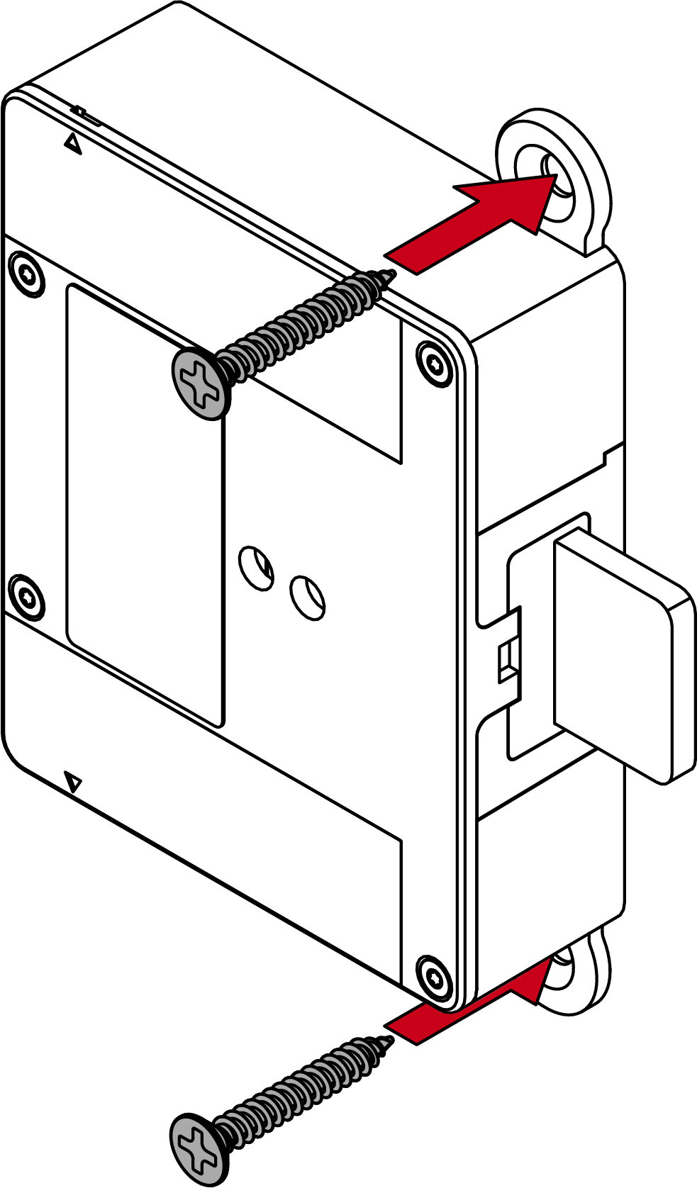
- Hook the screw into the holder and hold it in place.
- Fix the screw through the dead-bolt side hole on the back with the plastic mounting tool.
- If necessary, plug in the flange extensions on the engine block.
- For wooden doors: Insert the fastening pieces into the recesses provided.
- Hold the plastic mounting tool with one finger and place the engine block on the adapter plate or through the D-hole bushing.
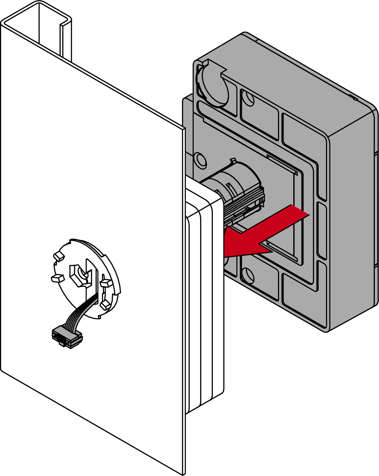
- Thread the socket cable through the socket.
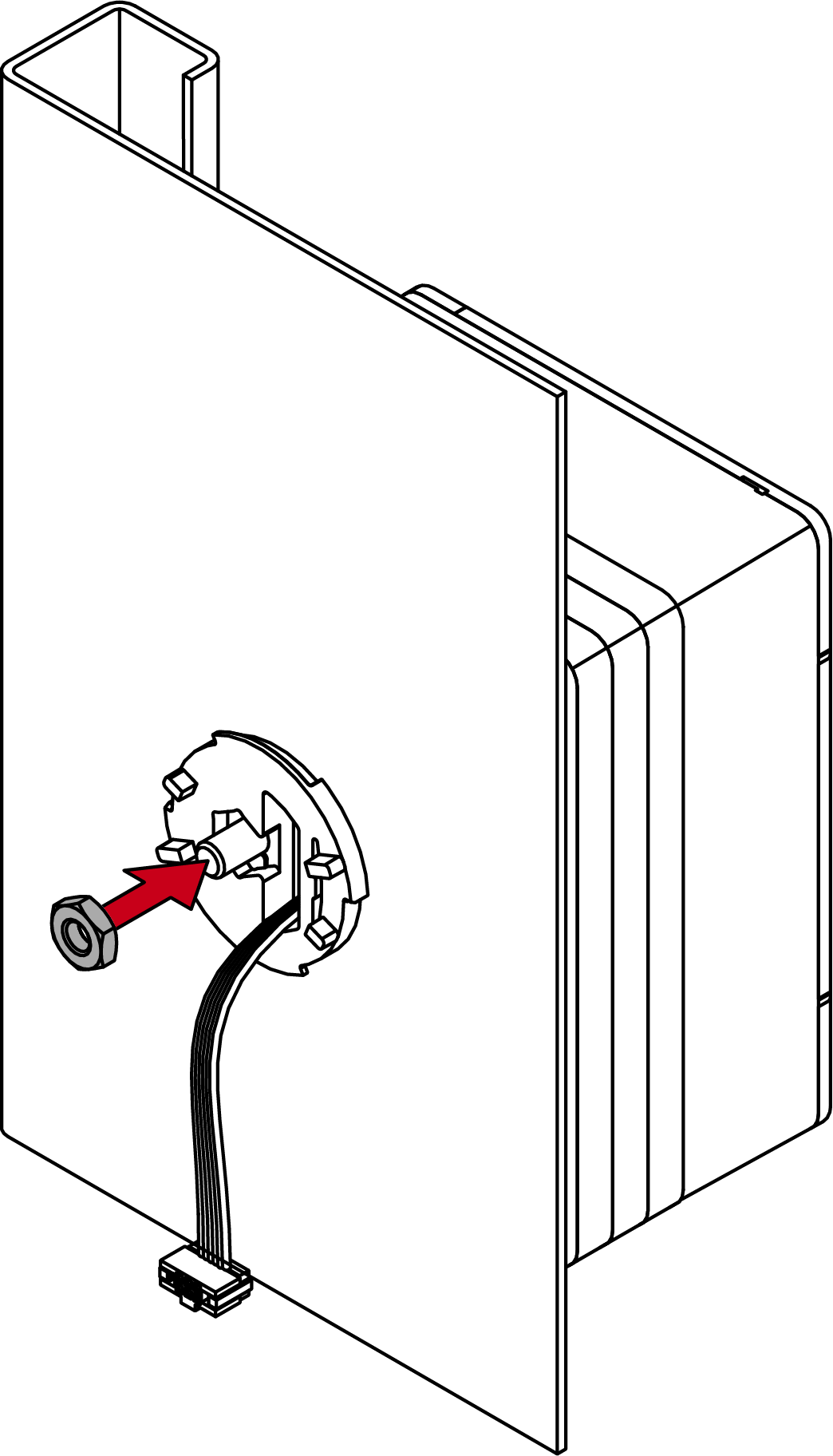
- Place the nut on the screw and carefully tighten the nut with the assembly tool already inserted until it sits on the hexagonal mount.
- For wooden doors: Straighten the motor block and firmly tighten the fastening pieces with suitable screws.
- Tighten the nut with 1 Nm (2.5 mm hex wrench).
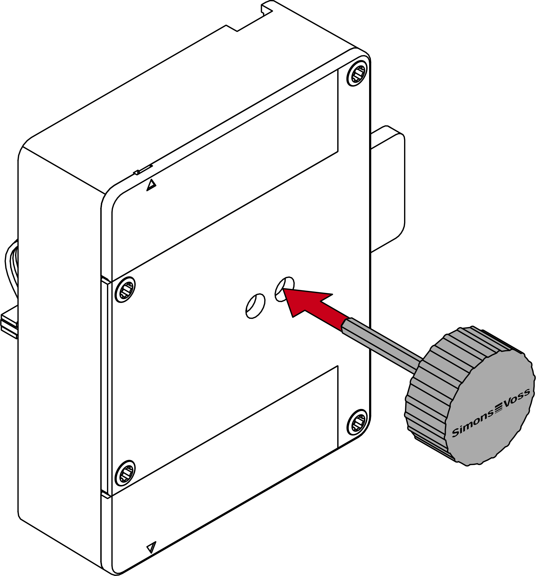
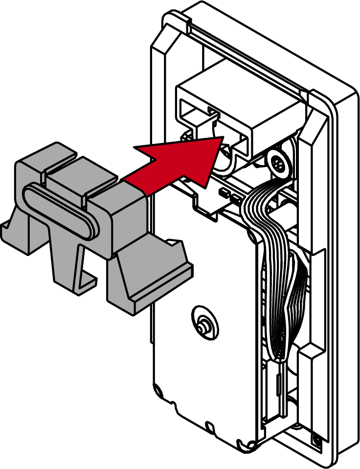
- Insert the clamping element and the plastic countersunk screw into the D-hole bushing from the front.
- Screw the tensioner until it stops (TX10 key) without screwing through the screw.
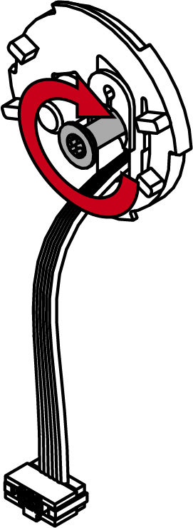
- Place the reader at an angle (approx. 60°).
- Turn the reader clockwise straight (bayonet mount).
- Route the cable past next to the area of the light guide.
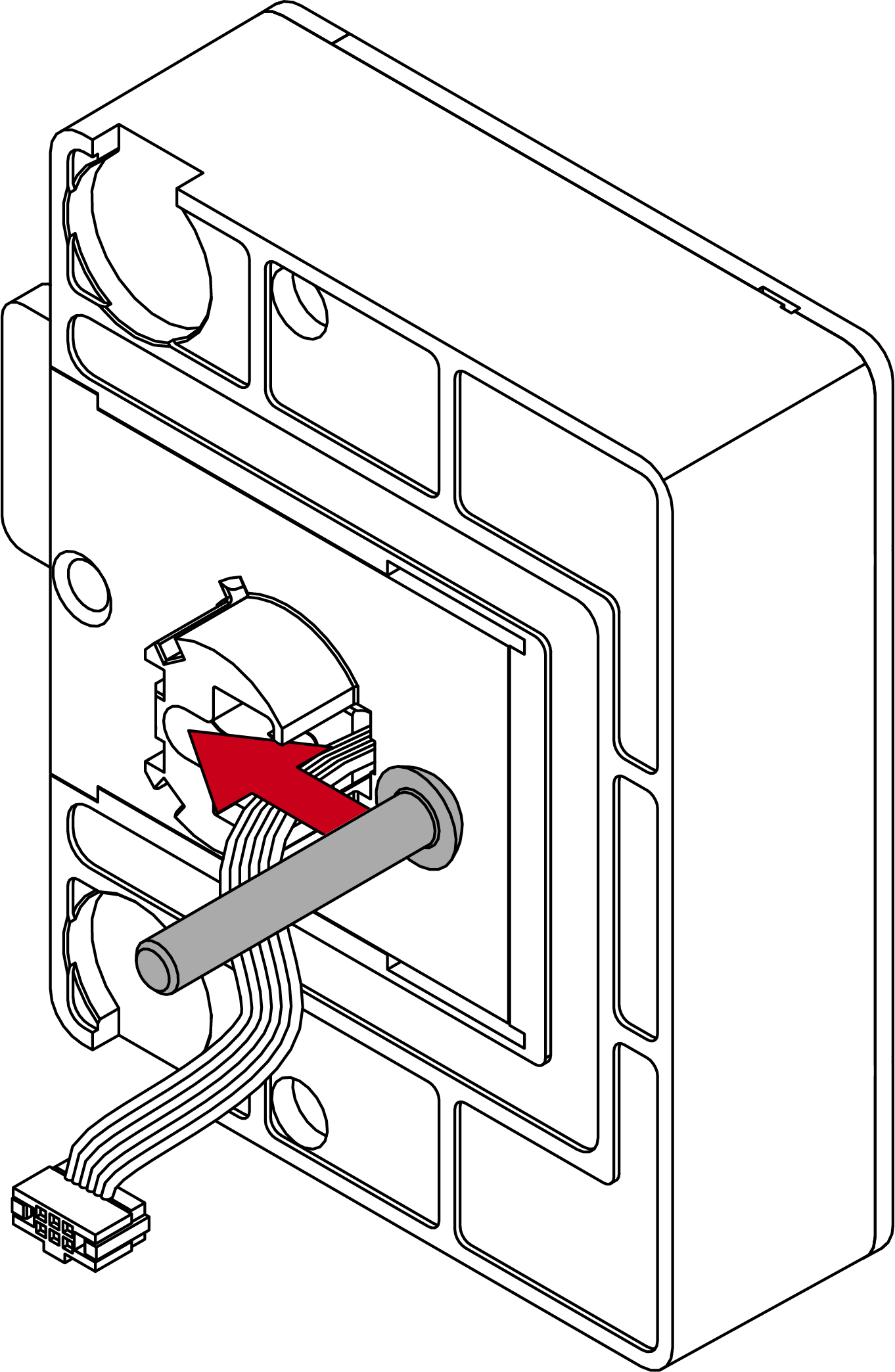
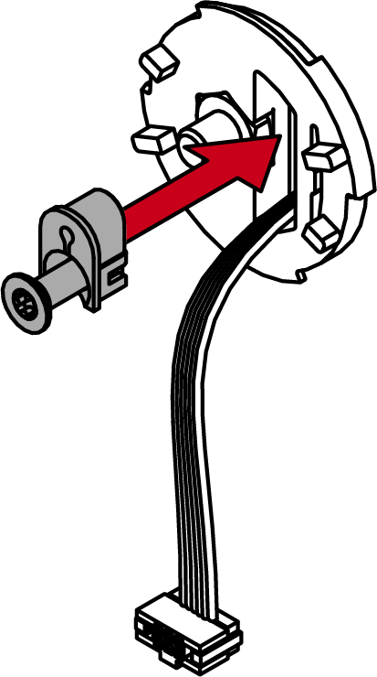
- Insert the plug into the socket with the lug facing the circuit board using the special tool.
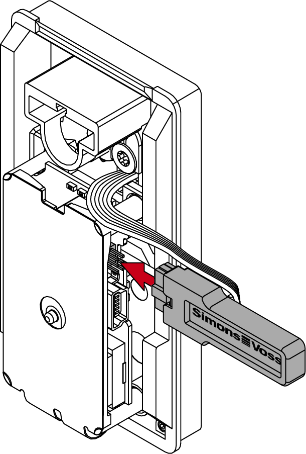
- The reader beeps and flashes three times.
- Attach the light guide and press it firmly.
- Reader protected against twisting.
- Store the excess cable in the gap next to the PCB.
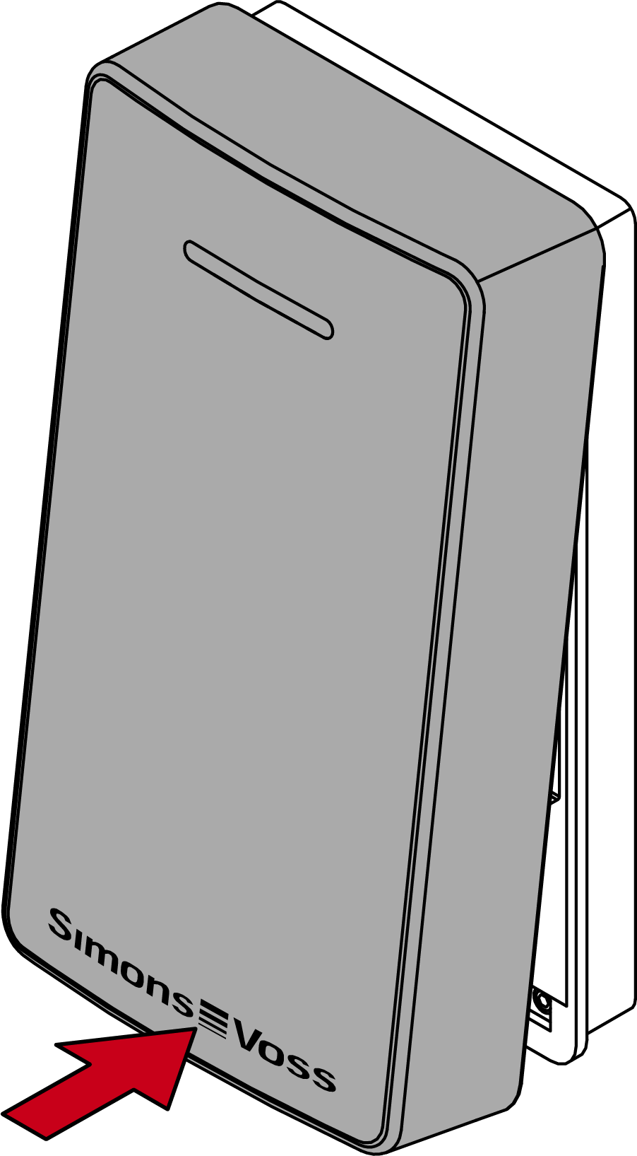
- Hook the lid on top.
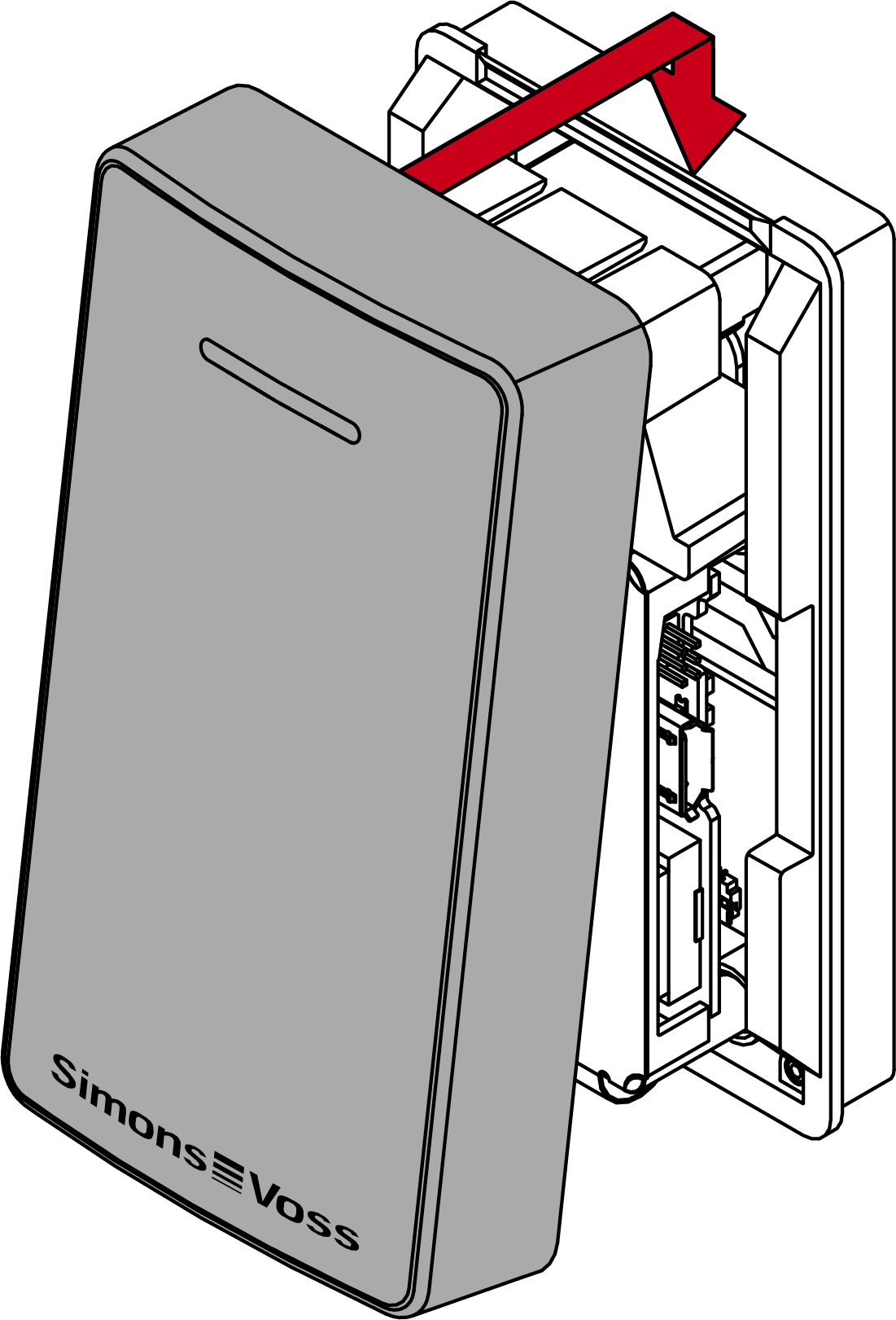
- Close the lid downwards.
- Gently press the lid against the floor and unscrew the lower screw counterclockwise (0.9 mm hex wrench) until it is flush with the lid surface.
- SmartLocker AX is completely assembled.