Installation - SmartBridge
The device can be fitted horizontally or vertically. You can fit it in a horizontal position easily and safely using the integrated mounting holes. Take into account the internal antenna’s directional characteristic (see Antenna) and align the device as appropriate.
IMPORTANT
Adverse effect on reception due to interferences
This device communicates wirelessly. Wireless communication can be affected or may fail due to metal surfaces or interference.
- Do not fit the device to metal surfaces.
- Keep the device away from sources of electrical or magnetic interference.
Unauthorised access
If the electrical contacts in the device are short-circuited by unauthorised persons, undesired reactions may occur.
- Mount the device in an environment that is protected from unauthorised access.
Malfunctions due to weather conditions
This device is not protected against splash water and other weather influences.
- Mount the device in an environment that is protected from the weather.
- Press the cover in as shown and remove it.

- Hold the base plate in the desired position and mark out the drill holes.
- Drill the necessary holes using a suitable drill bit.
- Use suitable fasteners and screw them into the base plate (countersunk head, drive: PH2, diameter: 4 mm; thread type and length depend on the chosen fastening method).
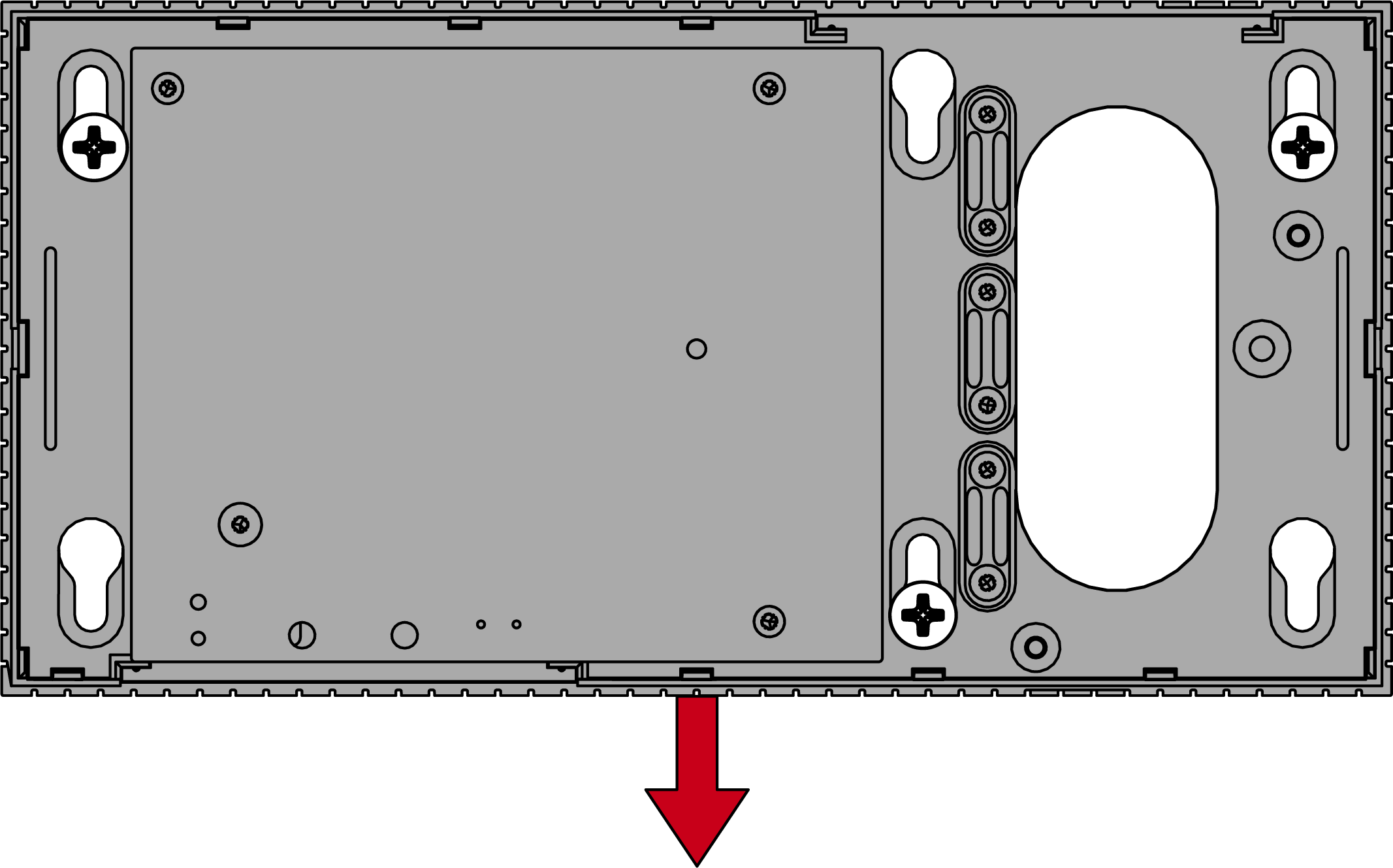
- Place the base plate so that the screw heads pass through the recesses.
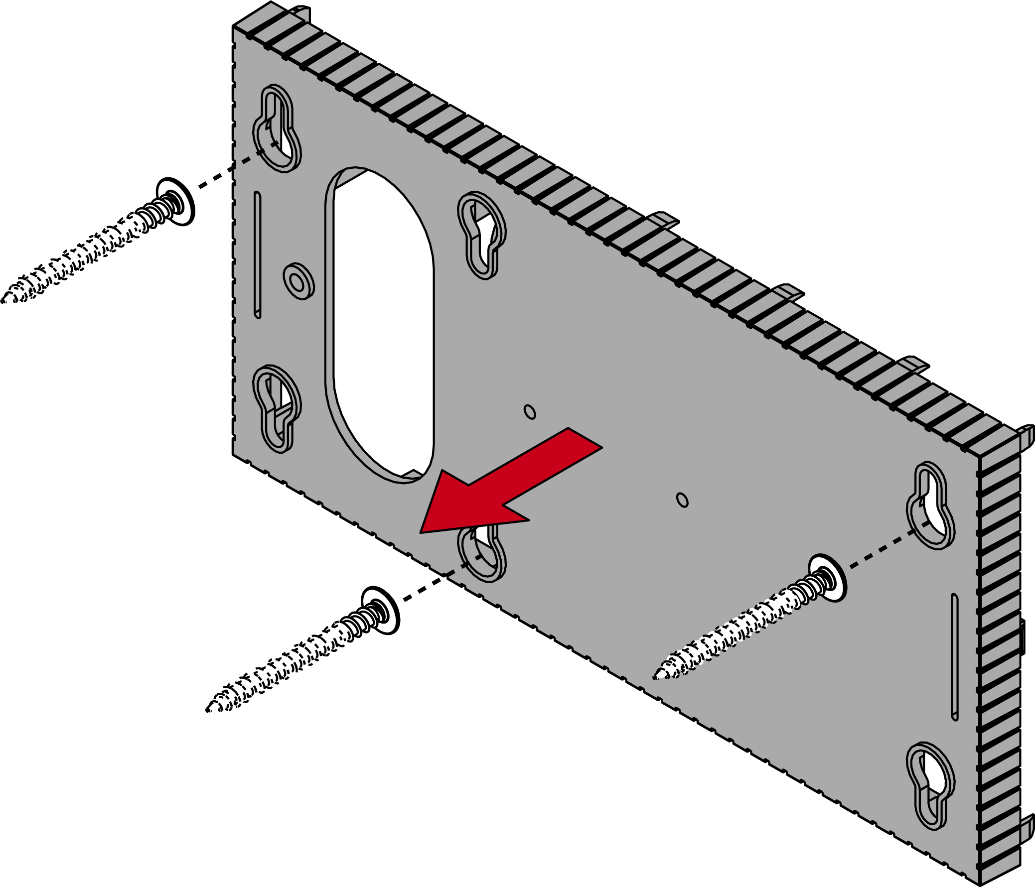
- Move the base plate so that the screw heads slide over the grooves.
CAUTION

Additional fixing for wall mounting
The appliance may fall from the wall.
- Tighten the screws after sliding the base plate into place.
- SimonsVoss recommends a maximum installation height of 2 m.
- Put the lid back on the base plate.
- Installation complete.
Wiring to device
You can install the cables both on (surface-mounted) and under (flush-mounted) plaster.
- If you install the cables under the plaster, then use the opening integrated in the base plate.
- If you lay the cables on the plaster, then you must modify the housing.
- Power supply disconnected.
- Push the ribbed area laterally inwards and remove the housing cover.
- Check the required width of the housing opening. The height of the opening is approx. 7 mm. Each removed bar widens the opening by 4 mm.
- Select a location where you want to remove the bars.
IMPORTANT
Insufficient fit due to removed clips
The housing cover is positioned and held by clips on the webs. If you saw off or break off these clips, the housing cover will no longer be held at this point.
- Do not remove any bars that have a clip over them.
- Do not damage clips during sawing.
- Use a suitable saw to saw through the bars at both ends of the desired opening to the base plate.
- Bend the bars back and forth at the desired opening until the bars break.

- The housing is designed to be mounted on a surface.